10
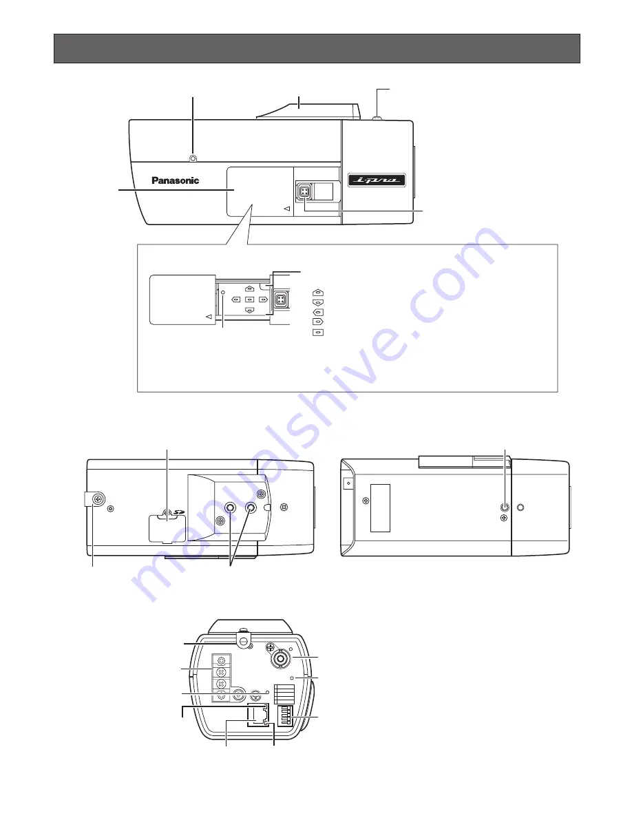
Major Operating Controls and Their Functions
<TOP>
<BOTTOM>
<REAR>
ALC lens connector
Tripod mount base
Microphone
INITIAL SET (UP)
(DOWN)
(LEFT)
NEAR
FAR
ABF/MENU
(SET) (RIGHT)
Cover for the
operation buttons
Fixing screw for transportation
* Remove the fixing screw before
connecting the power cable.
Inside the cover for the operation buttons
(Slide to the left until the cover is locked.)
[INITIAL SET] button
Operation buttons
* In these operating instructions, names of the buttons are as follows.
• About the [INITIAL SET] button
Turn on the power of the camera while holding down this button, and wait for around 5 seconds without releasing
this button. Wait another 30 seconds after releasing the button. The settings including the network settings will be
initialized. However, the settings edited on the [Camera] tab of the "Camera setup" page will not be initialized.
[UP] button
[DOWN] button
[LEFT/NEAR] button
[RIGHT/FAR] button
[SET, ABF/MENU] button
AC24V
IN
1-L
2-N
GND
1
2
3
4
5
1
2
3
4
5
GND
DAY/NIGHT IN
AUX OUT
ALARM OUT
ALARM IN
ACT
VIDEO OUT
10BASE-T/
100BASE-TX
LINK
POWER
SD CARD
AC 24 V terminal
Safety wire holder
Link indicator
Network connector
Video out connector
Power indicator (green)
Access indicator
External I/O terminals
SD memory card
error indicator (red)
SD memory card slot cover
Screw holes for the camera mounting bracket (1/4-20UNC)
Screw hole for the camera mounting bracket (1/4-20UNC)
Safety wire holder


