background image

21

Configure the Network Settings

Before installing the software, read the readme file on the
provided CD-ROM first.

Software included on the provided CD-ROM

• Panasonic IP setting software

Configure the network settings of the camera. Refer to
the following for further information.

• Viewer Software "Network Camera View2"

It is necessary to install the viewer software "Network
Camera Viewer2" to display images on a PC. Install the
viewer software by double-clicking the "Setup.exe" icon
on the provided CD-ROM.

Step 1

Start the Panasonic IP setting software.

Step 2

Click the [IP setting] button after selecting the MAC
address/IP address of the camera to be configured.

Note:

When using a DHCP server, the IP address assigned to
the camera can be displayed by clicking the [Refresh]
button of the IP setting software.
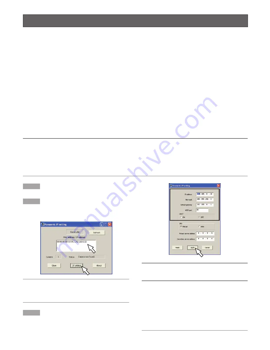
Step 3

Complete each network setup item and click the [Apply]
button.

Note:

When using a DHCP server, it is possible to set "DNS"
to "AUTO".

Important:

• It may take for around 30 seconds to complete to

upload the settings to the camera after clicking the
[Apply] button. The settings may be invalidated when
the AC adapter or the LAN cable is disconnected
before completing the upload. In this case, perform the
settings again.

• When using a firewall (including software), allow access

to all UDP ports.

Configure the network settings of the camera using the Panasonic IP set-
ting software

The network settings of the camera can be configured using the Panasonic IP setting software.
When using multiple cameras, it is necessary to configure the network settings of each camera independently.
When the Panasonic IP setting software does not work to perform the network settings of the camera, perform the network set-
tings of the camera and the PC individually on the "Network setup" page of the setup menu. Refer to the Network Operating
Instructions (PDF) for further information.

Important:

• When using Windows XP SP2, the "Windows Security Alert" window may be displayed when starting the IP setting software.

In this case, click the "Unblock" button on the displayed "Windows Security Alert" window.

• For the security enhancement, the MAC address/IP address of the camera to be configured will not be displayed when

around 20 minutes have passed after turning on the power of the camera.

• Panasonic IP setting software is inoperable in other subnets via the same router.

Install the software

Summary of Contents for i-pro WV-NP1004

Page 1: ...J E C T WV NP1004 Network camera Operating Instructions Model No WV NP1004 Lens is option Before attempting to connect or operate this product please read these instructions carefully and save this m...

Page 2: ...not expressly approved by the party responsible for compli ance could void the user s authority to operate this equip ment For U S A This Class A digital apparatus complies with Canadian ICES 003 For...

Page 3: ...your outlet consult an electrician for replacement of the obsolete outlet 10 Protect the power cord from being walked on or pinched particularly at plugs convenience receptacles and the point where th...

Page 4: ...OR NEGLIGENT OPERATION OF THE USER 3 UNAUTHORIZED DISASSEMBLE REPAIR OR MODIFI CATION OF THE PRODUCT BY THE USER 4 ANY PROBLEM CONSEQUENTIAL INCONVENIENCE OR LOSS OR DAMAGE ARISING OUT OF THE SYS TEM...

Page 5: ...a fixed focus lens 12 When using a manual lens 12 Installations Connections 13 Connection example 15 Insert Remove SD Memory Card 16 How to insert a SD memory card 16 How to remove the SD memory card...

Page 6: ...en the color image display and the BW image display Featured noise reduction function achieves high sensitivity Low noise circuit design achieved the minimum illumination of 1 0 lx F1 4 Auto shifting...

Page 7: ...T Compatible CPU Pentium 4 2 4GHz or faster Memory 512 MB or more Monitor 1 024 x 768 pixels or more 24 bit True color or better Network Interface 10 100Mbps Network interface card must be installed W...

Page 8: ...ion and malfunction Keep the appliance away from water and moisture To keep on using with stable performance Parts of this product may deteriorate and it may shorten lifetime of this product when usin...

Page 9: ...ing Instructions PDF for fur ther information about the port forwarding function Radio interference When the camera is used near TV radio antenna strong electric field or magnetic field near a motor o...

Page 10: ...onds without releasing this button Wait another 30 seconds after releasing the button The settings including the network settings will be initialized However the settings edited on the Camera tab of t...

Page 11: ...cus depending on the focal depth of the lens in use In this case focus on a darker object with the aperture open to prevent out of focus When ABF is selected for BACK FOCUS on the SETUP menu page 19 t...

Page 12: ...and set tings the focus to the FAR end When using a 2x or 3x varifocal lens adjust the flange back length after setting the zoom to the TELE end and settings the focus to the FAR end 3 Locate a subje...

Page 13: ...r equivalent strong part Method of installation may be different depending on the material of the place where the camera mounting bracket is to be installed When installing on steel Fix with bolts and...

Page 14: ...ending on the model and installa tion height of camera mounting bracket option Procure the optional safety wire kit suited for installa tion Refer to Select Safety Wire Kit for details Step 3 Connect...

Page 15: ...iptions of how to configure the router LAN cable category 5 cross PC 1 2 3 4 5 ACT VIDEO OUT 10BASE T 100BASE TX LINK POWER SD CARD GND AC24V IN 1 L 2 N 1 2 3 4 5 GND DAY NIGHT IN AUX OUT ALARM OUT AL...

Page 16: ...out SD memory card on the SD memory card tab of Basic Setup on the setup menu first Network Operating Instructions PDF r Attach the cover and tighten the screw q Loosen the screw of the SD memory card...

Page 17: ...Step 2 The focus position will be displayed at the bottom of the window and the flange back length will be automatically adjusted Step 3 When it is necessary to adjust the flange back length minutely...

Page 18: ...ALC and ELC according to the lens in use SHUTTER Select the shutter speed AGC Select the method of the gain adjustment SENS UP Adjust the sensitivity SYNC Display the method of the synchronization WH...

Page 19: ...ge the parameter Press the Left or Right button Display the detailed settings page of the setup item Press the SET button when the setup item with the O mark is selected Go back to the previous page M...

Page 20: ...1 2 CAMERA ID OFF ALC ELC ALC SHUTTER OFF AGC ON HIGH SENS UP OFF SYNC INT WHITE BAL ATW1 DNR HIGH BW MODE PRIVACY ZONE OFF EL ZOOM OFF MODEL WV NP1004 CAMERA BACK FOCUS SPECIAL NETWORK END SETUP DIS...

Page 21: ...e invalidated when the AC adapter or the LAN cable is disconnected before completing the upload In this case perform the settings again When using a firewall including software allow access to all UDP...

Page 22: ...g for repairs check the symptoms with the following table Contact your dealer if a problem cannot be solved even after checking and trying the solution or if the problem is not described below Check t...

Page 23: ...r the resolution setting White balance ATW1 ATW2 AWC DNR LOW HIGH Color BW AUTO1 AUTO2 EXT ON OFF Electronic Zoom x5 Image stabilizer ON OFF Camera ID Up to 16 characters ON OFF VMD alarm ON OFF 4 are...

Page 24: ...024 kbps 2 048 kbps 4 096 kbps 10 Mbps Unlimited Protocol TCP IP UDP IP HTTP RTP FTP SMTP DHCP DNS DDNS NTP SNMP OS Microsoft Windows 2000 Professional SP4 Microsoft Windows XP Home Edition SP2 Micro...

Page 25: ...Instructions English version 1 pc ALC lens connector cap 1 pc Warranty 1 pc The following is for the installation Cord label 1 pc The IP setting software the viewer software and the network operating...

Page 26: ...26...

Page 27: ...27...

Page 28: ...y of Panasonic Corporation of North America Security Systems www panasonic com security For customer support call 1 877 733 3689 Executive Office Three Panasonic Way 2H 2 Secaucus New Jersey 07094 Zon...

Reviews: