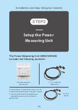
Setup the Power Measuring Unit
Installer Tasks
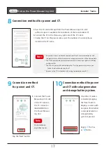
If the power wire straddles
the DIN rail, pass it
through the rear.* Power
wires must be solid core
and sized at 2.5mm².
Note
* Do not insert a power wire into the screwdriver aperture.
* Use a flat-head screwdriver with tip width 2.0 to 3.5mm.
* After connecting the power wire, check it cannot be removed by lightly tugging.
* Do not use a bent, damaged or otherwise deformed power wire.
* A damaged power wire can be trimmed.
* Inappropriate wiring may cause poor retention, poor connection or overheating.
Note
IMPORTANT
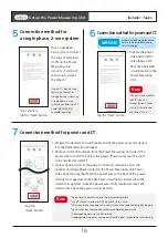
Connection method for
a single phase, 2-wire system.
5
Connection method for power and CT.
6
Connection method for power and CT.
7
For a single phase,
2-wire system, connect
the wires to terminals
V1-VN on the Power
Measuring Unit.
Use only I1 on the CT
and do not connect
the other CT.
1. Prepare the power
wire and form the
wire along a path
from the dedicated
circuit breaker to the
Power Measuring
Unit.
2. Prepare the dedicated circuit breaker end of the power wire and connect
it to the dedicated circuit breaker.
3. Remove 10mm of insulation from the Power Measuring Unit side of the
power wire to match the unit's strip gauge. (Power wires must be solid
core and sized at 2.5mm²)
4. Connect power wires to the power connection terminals, as per the
number of voltage phases stated on the Power Measuring Unit. Power
wire connection method: Push the power wire to the back of the power
terminal wire aperture while a flat-head screwdriver is inserted into the
screwdriver aperture. Once the power wire is fully inserted, remove the
screwdriver to lock the power wire in position.
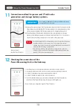
Unused CTs may be used
for solar generation or
storage battery systems on
a single phase, 2-wire
system by purchasing a CT
Cable (MKG1530-DE),
available separately.
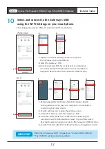
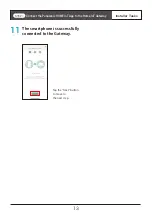
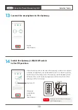
Once connect,
tap the “Next” button.
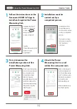
Tap the
“Next” button.
Tap the “Next” button.
Prepare a dedicated breaker to
ensure the power Measuring
Unit is powered.
STEP2
16

