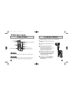
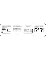
5. Insert the paper clips, etc. into the Tray as below figure
lift up the lever using the Eject Pin while pushing the dot
ted point of the Tray.
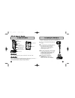
10.2.3. Pulley Gear, Belt
1. Perform the step “ 10. 2. 2. Tray”.
2. Push the Post to the direction of arrow by using the slot
ted screwdriver.
Post
3. Remove the Pulley Gear and Belt.
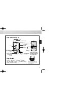
10.2.4. Slide Cam
1. Perform the step “10. 2. 3. Pulley Gear, Belt”.
2. Remove the Sheet.
3. Disconnect the 3 FFCs.
4. Remove the 2 Screws (B) and the Angle.
5. Remove the Drive P.C.B..
Sheet
FFC
Caution:
Though the Drive P.C.B. is not supplied as replace
ment parts, it must be removed for after disassem
bling.
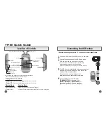
6. Open the connector lock, and disconnect the FFC.
7. Remove the 2 Screws (C), and remove the Traverse
Base Ass'y with spreading the 2 hooks to the direction of
arrows.
Traverse Base Ass’y
FFC
Screw (C)
31
Summary of Contents for DMP-BD45EE
Page 37: ...11 1 2 Checking and Repairing of BDP Digital P C B Module 37 ...
Page 50: ...S4 Schematic Diagram S4 1 Interconnection Diagram DMP BD45 BD65 INTERCONNECTION DIAGRAM S 6 ...
Page 51: ...S 7 ...
Page 57: ...S 13 ...
Page 59: ...2 4 DMP BD45EG BD65EG Series Power P C B Foil Side ...
Page 73: ...S8 Exploded View S8 1 Frame and Casing Section S 29 ...
Page 74: ...S8 2 Mechanism Section S 30 ...
Page 75: ...S8 3 Packing Parts and Accessories Section A a i A2 S 31 ...