background image

Operating Instructions

Excerpted Version

Installation Instructions provided

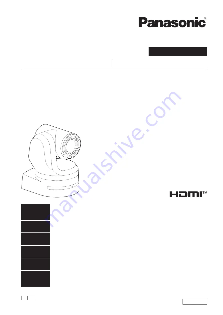
4K Integrated Camera

DVQX1709ZA

SS1018YM0 -FJ

Printed in Japan

ENGLISH

PJ EJ

ENGLISH

Excerpted Version

Before installing and using this product, be sure to read “Read this first!” (pages 4, 25 to 27).

This manual contains information excerpted from the Operating Instructions.

For more information, please visit the Panasonic website 

(https://pro-av.panasonic.net/manual/en/index.html)

, and 

refer to the Operating Instructions.

FRANÇAIS

Avant d’installer et d’utiliser cet appareil, s’assurer de lire la section « Lire ces informations en premier ! » (pages 4, 28 à 30).

Pour de plus amples informations, visiter le site Web de Panasonic 

(https://pro-av.panasonic.net/manual/en/index.

html)

 et consulter le mode d’emploi et les instructions d’installation.

ESPAÑOL

Antes de instalar y usar este producto, asegúrese de leer “Lea esto primero!” (páginas 4, 31 a 33).

Si desea obtener más información, visite el sitio web de Panasonic 

(https://pro-av.panasonic.net/manual/en/index.

html)

 y consulte las instrucciones de funcionamiento y las instrucciones de instalación.

DEUTSCH

Bitte lesen Sie sorgfältig „Bitte lesen Sie zuerst diesen Hinweis!“ vor der Installation und Nutzung dieses Produkts. (Seiten 5, 34 bis 35).

Weitere Informationen finden Sie auf der Panasonic-Webseite 

(https://pro-av.panasonic.net/manual/en/index.

html)

, in der Bedienungsanleitung und in der Installationsanleitung.

ITALIANO

Prima di installare e utilizzare il prodotto, assicurarsi di leggere “Leggere prima quanto segue!” (pagine 5, 36 a 37).

Per maggiori informazioni, visitare il sito Web Panasonic 

(https://pro-av.panasonic.net/manual/en/index.html)

 e 

fare riferimento alle istruzioni per l’uso e alle istruzioni per l’installazione.

PУССКИЙ

Перед установкой и использованием данного изделия ознакомьтесь с информацией в разделе «Прочитайте 

нижеследующее до начала эксплуатации!» (стр. 5, 38 до 39).

Для получения дополнительной информации посетите веб-сайт Panasonic 

(https://pro-av.panasonic.net/

manual/en/index.html)

 и обратитесь к инструкции по эксплуатации и инструкции по установке.

Before operating this product, please read the instructions carefully and save this manual for future use.

Model No.

  AW‑UE150WP

Model No.

  AW‑UE150KP

Model No.

  AW‑UE150WE

Model No.

  AW‑UE150KE

Summary of Contents for AW-UE150WP

Page 1: ...lte las instrucciones de funcionamiento y las instrucciones de instalación DEUTSCH Bitte lesen Sie sorgfältig Bitte lesen Sie zuerst diesen Hinweis vor der Installation und Nutzung dieses Produkts Seiten 5 34 bis 35 Weitere Informationen finden Sie auf der Panasonic Webseite https pro av panasonic net manual en index html in der Bedienungsanleitung und in der Installationsanleitung ITALIANO Prima ...

Page 2: ...hich can be used by Windows Internet Explorer 11 only are indicated using the mark The screenshots are used in accordance with the guidelines of Microsoft Corporation български Посетете следния уебсайт относно информация за безопасността и важни уведомления за продукта Hrvatski Za sigurnosne informacije i važne obavijesti o proizvodu posjetite sljedeću internetsku stranicu Čeština Na následujícím ...

Page 3: ...ad this first For AW UE150WE AW UE150KE 26 Lire ces informations en premier Pour AW UE150WP AW UE150KP 28 Lire ces informations en premier Pour AW UE150WE AW UE150KE 29 Lea esto primero Para AW UE150WP AW UE150KP 31 Lea esto primero Para AW UE150WE AW UE150KE 32 Bitte lesen Sie zuerst diesen Hinweis Für AW UE150WE AW UE150KE 34 Leggere prima quanto segue Per AW UE150WE AW UE150KE 36 Прочитайте ниж...

Page 4: ... installation peut avoir pour conséquence la chute de l appareil et provoquer des blessures ATTENTION Cette caméra est conçue pour être utilisée uniquement avec la potence de fixation fournie avec l appareil ou avec la potence de fixation directe au plafond Panasonic WV Q105A L utilisation de tout autre dispositif risque de se traduire par une instabilité et être cause de blessures à des personnes...

Page 5: ...ncorretta può risultare nella caduta dell apparecchio con conseguenti danni alle persone PRECAUZIONE La videocamera deve essere utilizzata esclusivamente con la staffa di montaggio in dotazione con l unità e con la staffa per montaggio diretto a soffitto WV Q105A L uso con altri apparecchi potrebbe causare instabilità ed eventuali infortuni sono le informazioni sulla sicurezza Прочитайте нижеследу...

Page 6: ...r conferring in detail with your dealer Install the unit on a ceiling that is strong enough such as a concrete ceiling If the unit is to be installed on a ceiling which is not strong enough reinforce the ceiling sufficiently first Do not install or use the unit in the following kinds of locations On walls where the unit would be installed sideways In locations including places such as under the ea...

Page 7: ... Standby mode the unit will be in Standby mode the next time power is supplied Status display lamp Lit orange When the power supply is cut off while the unit is in Power ON mode the unit will be in Power ON mode the next time power is supplied Status display lamp Lit green For details refer to How to turn the power on and off page 59 Grounding Before operating the unit check that SIGNAL GND has be...

Page 8: ...rvice switch Function Factory settings SW1 Switches for initialization Refer to the explanations in Initialization 1 and Initialization 2 OFF SW2 Always leave at OFF used for factory adjustments OFF SW3 OFF SW4 OFF Initialization 1 Reset the user authentication settings and host authentication settings for network connection This will delete all the registered user information IDs passwords and ho...

Page 9: ...he unit is to be installed and in which direction it should be mounted Factor in the unit mounting area and include space for the wires extending from its rear panel The asterisk in the illustration marks the position and dimensions of the hole for mounting the mount bracket 160 6 5 16 Space for the wires from the rear panel 320 12 19 32 or more Space for the wires 90 3 17 32 88 3 15 32 136 5 11 3...

Page 10: ...e which has been attached to the bottom panel of the unit around the end of the hook part of the mount bracket Pull the drop prevention wire and check that it has been attached securely to the hook End of hook Drop prevention wire A Loop the circle part of the drop prevention wire around the end of the hook part of the mount bracket B Pull the wire and check that it is securely attached to the hoo...

Page 11: ...w M3 screw with flat washer spring washer Status display lamp Approx 20 On the camera main unit Holes 3 used to insert the bottom panel On the mount bracket Protrusions 3 used for inserting the camera Hole for checking the positioning NOTE Do not do this work while holding the camera head since doing so may result in malfunctioning of the unit Use only the screws supplied Do not use any other scre...

Page 12: ...en Optical output is to be used connect the recommended optical fiber module page 49 For details on recommended products refer to the catalog or consult your local dealer LAN cable DC cable External DC power supply HDMI cable Optical fiber multi cable Coaxial cable 12 How to install and connect the unit continued ...

Page 13: ... ceiling mount bracket and attach the WV Q105A as well as the drop prevention wire angle and drop prevention wire supplied with the WV Q105A to the anchor bolts Mounting the anchor bolts and direct ceiling mount bracket This job is facilitated if the direct ceiling mount bracket is loosely secured to the ceiling panel in one place and the direct ceiling mount bracket and anchor bolts are verticall...

Page 14: ...nstalled position B and remove it C Main unit mounting screw M3 screw with flat washer spring washer Approx 20 NOTE Do not do this work while holding the camera head since doing so may result in malfunctioning of the unit 5 Disengage the drop prevention wire from the mount bracket A Pull the dropprevention wire in the direction shown by the arrow above B Twist the wire and remove the wire loop thr...

Page 15: ...p prevention wire 4 Mount the unit Align the position of the hole for checking the positioning with the status display lamp Align the holes on the camera main unit used to insert the bottom panel with the protrusions on the mount bracket used for inserting the camera push the bracket and camera firmly together and rotate the main unit by about 20 degrees in the direction of the arrow Secure the mo...

Page 16: ...tical output is to be used connect the recommended optical fiber module page 49 For details on recommended products refer to the catalog or consult your local dealer Optical fiber multi cable Coaxial cable HDMI cable DC cable External DC power supply LAN cable 16 Stand alone installation when the mount bracket is going to be used continued ...

Page 17: ...hen mounting the unit on a tripod Attach the tripod to the threaded holes for mounting the camera on the camera s bottom panel Place the tripod on a completely flat and level surface Tighten the screws by hand to mount the tripod securely Use screw for mounting the tripod that satisfy the following standard Screw for mounting tripod 1 4 20UNC ISO1222 6 35 mm 1 4 inches 4 5 mm to 9 mm 3 16 inches t...

Page 18: ...s Connections Connecting an NDI HX compatible switcher External DC power supply AW UE150 AW UE150 LAN cable Switching hub NDI HX compatible switcher Monitor Monitor External DC power supply Remote Camera Controller AW RP150 18 ...

Page 19: ...UE150 AW UE150 Remote camera controller AW RP150 External DC power supply External DC power supply Monitor Monitor MONI OUT 3G SDI OUT 3G SDI ACTIVE THRU OUT SDI IN LAN cable Straight cable or cross cable Max 100 m 328 ft LAN cable Straight cable or cross cable Max 100 m 328 ft Use a category 5e cable for the LAN cable 19 Connections continued ...

Page 20: ... Live Switcher AW HS50 Monitor 1 Monitor 2 Monitor Monitor Pan tilt head and camera control signal LAN straight cable System TALLY External DC power supply Remote Camera Controller AW RP150 Genlock signal generator External DC power supply RS 422 connector Accessory AC adaptor 20 Connections continued ...

Page 21: ...k signal generator SDI video signal Switching hub LAN cable Compact Live Switcher AW HS50 Monitor 1 Monitor 2 Monitor Monitor LAN cable Remote Camera Controller AW RP150 External DC power supply Accessory AC adaptor External DC power supply LAN connector 21 Connections continued ...

Page 22: ...Installation Instructions System example 3 IP image transmission PoE AW UE150 AW UE150 PoE compatible switching hub or PoE injector LAN cable Personal computer LAN connector 22 Connections continued ...

Page 23: ...mm inch POWER STANDBY 12 V IN IR ID AUDIO IN RS 422 SERVICE MONI OUT 12G SDI OUT 3G SDI OUT G L IN LAN LINK ACT OPTICAL 182 7 5 32 86 95 3 7 16 177 6 31 32 90 9 3 19 32 219 6 8 21 32 210 5 8 9 32 2 3 32 213 8 3 8 266 6 10 1 2 Rear panel view 23 ...

Page 24: ...Operating Instructions Read this first Note on grounding Ground the unit via the SIGNAL GND ground connector IR ID AUDIO IN Ground connector to ground connector on wall outlet ground bar etc 24 ...

Page 25: ... the tripod which may result in injury indicates safety information FCC NOTICE USA Declaration of Conformity Model Number AW UE150P Trade Name Panasonic Responsible Party Panasonic Corporation of North America Two Riverfront Plaza Newark NJ 07102 Support contact 1 800 524 1448 This device complies with part 15 of the FCC Rules Operation is subject to the following two conditions 1 This device may ...

Page 26: ...ing To reduce the risk of electric shock do not remove the covers No user serviceable parts inside Refer servicing to qualified service personnel CAUTION In order to maintain adequate ventilation do not install or place this unit in a bookcase built in cabinet or any other confined space To prevent risk of electric shock or fire hazard due to overheating ensure that curtains and any other material...

Page 27: ...andards However the apparatus may be adversely affected by interference if it is being used in an EMC environment such as an area where strong electromagnetic fields are generated by the presence of signal transmission towers cellular phones etc In order to minimize the adverse effects of the interference on the apparatus in cases like this it is recommended that the following steps be taken with ...

Page 28: ...n ne pas retirer le couvercle Il ne se trouve à l intérieur aucune pièce qui puisse être réparée par l utilisateur Confier toute réparation à un personnel qualifié ATTENTION Pour maintenir une bonne ventilation ne pas installer ni placer l appareil dans une étagère un meuble encastré ni aucun endroit confiné Pour éviter tout risque de choc électrique ou de feu dû à une surchauffe vérifier qu aucun...

Page 29: ...rences radio ATTENTION Ne pas dévisser le couvercle Pour réduire tout risque d électrocution ne pas retirer le couvercle Il ne se trouve à l intérieur aucune pièce qui puisse être réparée par l utilisateur Confier toute réparation à un personnel qualifié ATTENTION Pour maintenir une bonne ventilation ne pas installer ni placer l appareil dans une étagère un meuble encastré ni aucun endroit confiné...

Page 30: ...négative par des interférences s il est utilisé dans un environnement CEM tel qu une zone où de forts champs électromagnétiques sont générés par la présence de pylônes de transmission téléphones portables etc Pour réduire au minimum les effets négatifs des interférences sur l appareil dans des cas de ce genre il est conseillé d adopter les mesures suivantes en ce qui concerne l appareil concerné e...

Page 31: ...as eléctricas Las piezas del interior no requieren mantenimiento por parte del usuario Solicite las reparaciones al personal de servicio calificado PRECAUCIÓN Para mantener unas buenas condiciones de ventilación no instale ni ponga este aparato en una librería mueble empotrado u otro espacio reducido Para evitar el riesgo de que se produzcan sacudidas eléctricas o peligros de incendio debidos al r...

Page 32: ...a desatornillándola No quite la tapa para evitar el riesgo de sacudidas eléctricas Las piezas del interior no requieren mantenimiento por parte del usuario Solicite las reparaciones al personal de servicio calificado PRECAUCIÓN Para mantener unas buenas condiciones de ventilación no instale ni ponga este aparato en una librería mueble empotrado u otro espacio reducido Para evitar el riesgo de que ...

Page 33: ...mejor respecto al nivel de rendimiento requerido por estas normas Sin embargo el aparato puede quedar perjudicado por las interferencias si se está utilizando en un ambiente CEM como una zona donde haya fuertes campos electromagnéticos generados por la presencia de torres de transmisión de señales teléfonos móviles etc Para minimizar los efectos negativos de la interferencia en el aparato en casos...

Page 34: ...Zur Vermeidung von elektrischem Schlag darf das Gehäuse nicht geöffnet werden Im Geräteinneren befinden sich keine Teile die vom Benutzer gewartet werden können Wartungs und Reparaturarbeiten grundsätzlich autorisiertem Kundendienstpersonal überlassen VORSICHT Um eine ausreichende Belüftung zu gewährleisten dieses Gerät nicht in einem Bücherregal Einbauschrank oder an einem anderen engen Platz auf...

Page 35: ...telefone etc störend beeinflusst werden Um in diesen Situationen die störenden Einflüsse auf das Gerät zu minimieren wird empfohlen folgende Schritte für betroffene Geräte und Betriebsumgebungen durchzuführen 1 Positionieren Sie das Gerät von der Störquelle entfernt 2 Ändern Sie die Geräterichtung 3 Ändern Sie die Anschlussmethode des Geräts 4 Schließen Sie das Gerät an eine andere Stromverbindung...

Page 36: ...hio svitandolo Per ridurre i pericoli di scosse elettriche non togliere il coperchio All interno non ci sono parti riparabili dall utente Per le riparazioni rivolgersi a personale tecnico qualificato PRECAUZIONE Per assicurare una buona ventilazione non installare o sistemare questo apparecchio in uno scaffale mobile incorporato od altro spazio chiuso Per evitare i pericoli di scosse elettriche o ...

Page 37: ...ni dell apparato è equivalente o superiore al livello di prestazioni richiesto da questi standard Tuttavia l apparato potrebbe essere disturbato da interferenze esterne qualora venga utilizzato in un ambiente EMC come nel caso di un area con forti campi elettromagnetici generati dalla presenza di torri per la trasmissione di segnali telefoni cellulari ecc In casi simili al fine di minimizzare il d...

Page 38: ...ей Для снижения риска удара электрическим током не снимайте панели Внутри устройства нет деталей подлежащих обслуживанию пользователем Обратитесь за сервисным обслуживанием к квалифицированному персоналу ВНИМАНИЕ Для обеспечения надлежащей вентиляции не устанавливайте и не размещайте данное устройство на книжном стеллаже во встроенном шкафу или в другом закрытом пространстве Для предотвращения рис...

Page 39: ... феррита Если камера поставляется с ферритовыми сердечниками следует подсоединить их к кабелям как показано в инструкции 2 Уровень производительности Уровень производительности данного устройства соответствует требованиям указанных стандартов или превосходит их При использовании устройства вблизи оборудования которое является источником сильного электромагнитного излучения могут возникать помехи н...

Page 40: ...nal computer via an IP network it can be operated via a web browser With a variety of 4K interfaces there are individual outputs for HD and SDI so the unit can be used flexibly in a wide range of situations as a 4K compatible remote camera Connection with a Panasonic camera controller is also possible via Panasonic s proprietary serial communication format The unit is available in white AW UE150WP...

Page 41: ...t B Unauthorized operation of the unit by persons with malicious intent C Interference with or stoppage of the unit by persons with malicious intent It is your responsibility to take precautions such as those described below to protect yourself against the above network security risks Panasonic does not accept any responsibility for damage of this type Use the unit in a network secured by a firewa...

Page 42: ...NOTE It may be necessary to upgrade the version of the controllers other than AW RP150 in order to support the unit For details on upgrading visit the support page on the following website https pro av panasonic net The maximum distances between the units and controller is 1000 meters 3280 ft when serial control is exercised Use of an external device or some other means must be provided separately...

Page 43: ...ain unit mounting screw with flat washer spring washer M3 6 mm 1 4 inches 1 Drop prevention wire 1 Drop prevention wire mounting screw 1 comes attached to the unit Bracket mounting screws bind head M4 10 mm 13 32 inches 4 Optional accessories z zWireless remote control AW RM50G Size AA dry battery x 2 obtained separately z zDirect ceiling mount bracket WV Q105A z zFiber module NOTE For details on ...

Page 44: ...s power is turned on the zoom focus and iris are adjusted automatically The unit comes with the safe mode The safe mode is function designed to protect the unit from damage For details refer to the Operating Instructions PDF Safe mode Concerning the safe mode Operating temperature range Avoid using the unit in cold locations where the temperature drops below 0 C 32 F or hot locations where the tem...

Page 45: ... Failure to obey may result in injuries Wipe the surfaces using a soft dry cloth Avoid all contact with benzine paint thinners and other volatile substances and avoid using these substances Otherwise the casing may become discolored Do not turn the camera head by hand Turning the camera head by hand may cause the unit to malfunction Use the unit in an environment with minimal moisture and dust Avo...

Page 46: ...rescent lights plasma monitors or other such products or if the unit is exposed to sunlight the effects of the light may make it impossible for the unit to be operated using the wireless remote control Be sure to follow the steps below for installation and use Take steps to ensure that the wireless remote control signal light sensing area will not be exposed to the light from fluorescent lights pl...

Page 47: ...ceived from the wireless remote control optional accessory while the power is on Blinking rapidly When the initialization process is complete Red Light up When trouble has occurred in the unit Blinking slowly Firmware being updated Blinking rapidly When a PoE software authentication error has occurred 4 Tilt head This rotates in the right and left direction 5 Wireless remote control signal light s...

Page 48: ... unit on 12 V IN IR ID AUDIO IN RS 422 SERVICE MONI OUT 12G SDI OUT 3G SDI OUT G L IN LAN LINK ACT OPTICAL Service switches Function Factory settings SW1 Switches for initialization Refer to the explanations in Initialization 1 and Initialization 2 OFF SW2 Always leave at OFF used for factory adjustments OFF SW3 OFF SW4 OFF Initialization 1 Reset the user authentication settings and host authentic...

Page 49: ... external DC power supply that can assure double the capacity of the total power consumption of the camera and connected devices that are turned on by interlock when the power of the camera is turned on such as lenses wireless microphone receivers Make sure of the pin alignment of the DC output terminal of the external DC power supply and the camera DC IN connector and connect the polarity correct...

Page 50: ... over 59 94i 1080 23 98p over 59 94i 720 59 94p 720 59 94p 720 59 94p 720 59 94p 720 59 94p 720 59 94p 50Hz 2160 50p 2160 50p 2160 50p 2160 50p 1080 50p 1080 50i 1080 50i 2160 25p 2160 25p 2160 25p 2160 25p 1080 25p 1080 25PsF 1080 25p 1080 25PsF 1080 50p 1080 50p 1080 50p 1080 50p 1080 50p 1080 50i 1080 50i 1080 50i 1080 50i 1080 50i 1080 50i 1080 50i 1080 50i 1080 25p 1080 25p 1080 25p 1080 25p ...

Page 51: ... 720 1280 720 1280 720 1280 720 1280 720 640 360 640 360 640 360 640 360 640 360 640 360 320 180 320 180 320 180 320 180 320 180 320 180 Frame rate System frequency 59 94Hz 60fps 60fps 30fps 30fps 30fps 30fps 30fps 30fps 30fps 15fps 15fps 15fps 15fps 15fps 15fps 15fps 5fps 5fps 5fps 5fps 5fps 5fps 5fps 1fps 1fps 1fps System frequency 50Hz 50fps 50fps 25fps 25fps 25fps 25fps 25fps 25fps 25fps 12 5f...

Page 52: ...ted When Streaming mode is set to JPEG UHD Settings H 265 H 264 1 H 264 2 H 264 3 H 264 4 JPEG 1 JPEG 2 JPEG 3 Resolution 3840 2160 1920 1080 1920 1080 1280 720 1280 720 1280 720 1280 720 640 360 640 360 640 360 320 180 320 180 320 180 Frame rate System frequency 59 94Hz 60fps 60fps 30fps 30fps 30fps 30fps 15fps 15fps 15fps 15fps 5fps 5fps 5fps 5fps 5fps 1fps System frequency 50Hz 50fps 50fps 25fp...

Page 53: ...frequency 24 23 98Hz 24fps 24fps 24fps 24fps 12fps 12fps 12fps 4fps 4fps 4fps 1fps 1fps 1fps The available options for the H 264 transmission mode Transmission priority are limited to 30fps or lower excluding 24fps When the system frequency is 24 23 98Hz the resolution for H 264 1 and H 264 2 is limited to 1920 1080 When Streaming mode is set to NDI HX Settings NDI HX JPEG 1 Resolution 1920 1080 1...

Page 54: ...djusted automatically 6 MODE button MODE This is used to select the video signals which are output from the unit Each time it is pressed the signals are switched between the color bar signals and camera video signals NOTE When Audio is set to On and the color bar is displayed a test sound 1 kHz is output Be cautious of the volume on external devices 7 GAIN button OFF LOW HI AUTO These are used to ...

Page 55: ...the lens focus manually when the manual setting is established for the lens focus The focus is adjusted in the far using the F button and in the near using the N button 12 A FOCUS button A FOCUS This is used when automatically adjusting the lens focus 13 M FOCUS button M FOCUS This is used when manually adjusting the lens focus The FOCUS buttons F and N are used when performing the actual adjustme...

Page 56: ...s set a different remote control ID for each control When using one unit set the remote control ID to CAM1 unless the setting needs to be changed Setting procedure Operate the IR ID switches on the unit s rear panel and select CAM1 CAM2 CAM3 or CAM4 as the remote control ID page 49 The IR ID switch settings CAM1 to CAM4 correspond to the CAM1 to CAM4 buttons on the wireless remote control The fact...

Page 57: ...sible to make network settings for the target camera once about 20 minutes or more have elapsed after turning the power of the camera on Operating Instructions PDF Web screen configurations Network setup screen Network Common to IPv6 IPv4 Easy IP Setup accommodate period The Easy IP Setup Software cannot be used from a different subnet via a router Use Easy IP Setup Software ver 4 25R00 or newer 1...

Page 58: ...onds elapse after the completed screen is displayed If the live screen Live is not displayed after 10 seconds elapse manually move to the live screen Live by clicking the please click here link This completes the process of registering the initial account Installing the plug in viewer software To view IP images from the unit on Windows Internet Explorer 11 the Network Camera View 4S plug in viewer...

Page 59: ... the remote control ID has been received NOTE When operation is transferred to the Standby mode The current zoom focus and iris positions are stored in the memory Power ON preset When operation is transferred to the Power ON mode The zoom focus and iris are adjusted to the positions which were stored in the memory Power ON preset when operation was transferred to the Standby mode When performing o...

Page 60: ...ers Has the unit you want to operate been selected properly Operating Instructions PDF Selecting the units Cannot operate using the wireless remote control Have the remote control s batteries run down or have the batteries been installed with their polarities reversed If the status display lamp does not blink even when the wireless remote control is operated near the wireless remote control signal...

Page 61: ...lems in operation If a reply is not received try following operation Reboot the unit and within 20 minutes change the IP address using the Easy IP Setup Software Are you accessing via http while the HTTPS function is enabled Perform access via https when using the HTTPS function Entry of the port number is also required Operating Instructions PDF Web screen configurations Network setup screen Netw...

Page 62: ...Internet Options in Internet Explorer B Click the General tab and click the Settings button under Browsing history C In the Temporary Internet Files and History Settings dialog box select the Every time I visit the webpage option under Check for newer versions of stored pages D Click the OK button The unit s ports may be filtered by the firewall or other function of the anti virus software Change ...

Page 63: ...it again Operating Instructions PDF Web screen configurations User management screen User mng User authentication screen User auth Add User User name Password Retype password Has the method for user authentication been changed If you change the User auth Authentication setting close the web browser and initiate access again Operating Instructions PDF Web screen configurations User management scree...

Page 64: ...as the background image changes Depending on the edge enhancement setting established for the monitor white lines appear in front of the black shadows of the camera menus Depending on the edge enhancement setting established for the monitor the background colors may be superimposed onto the white parts of the camera menus No auto focusing Is the focus set to manual Auto focusing is initiated as so...

Page 65: ...ture is set to open in night mode to prevent video voyeurism Adjust the brightness at the light source Operating Instructions PDF Manual shooting Manually adjusting the iris The iris does not operate in night mode The subjects appear distorted Since this camera uses an MOS imaging device the pickup timing differs slightly at the top left and bottom right of the screen This means that if a subject ...

Page 66: ... the network congestion the level of access to the unit etc If the IP video settings of the unit were changed the image display may stop temporarily Check the level of access to the unit and stop any unnecessary access Afterward check the following For Windows Press the F5 key on the personal computer s keyboard to request that the settings be acquired For Mac Press the Command R key on the person...

Page 67: ...l Internet service provider for both the camera and the personal computer may prevent this problem Consult your network administrator When multiple web browsers are running to display H 264 images images from multiple cameras appear sequentially in a single web browser For Windows This may occur depending on the combination of the personal computer s display adaptor and the driver If this occurs u...

Page 68: ...g window appears click the Install button An unnecessary status bar or scroll bar is displayed on the pop up window Open the security settings screen for Internet Explorer and select Internet Click the Custom level button set Allow script initiated windows without size or position constraints to Enable under Miscellaneous and click the OK button When the warning window appears click the Yes button...

Page 69: ...IN connector 1 2 A PoE power supply indicates safety information GENERAL Ambient operating temperature 0 C to 40 C 32 F to 104 F Storage temperature 20 C to 50 C 4 F to 122 F Ambient operating humidity 20 to 90 no condensation Mass Approx 4 2 kg 9 24 lb excluding mount bracket Dimensions W H D 213 mm 267 mm 219 mm 8 3 8 inches 10 1 2 inches 8 5 8 inches excluding protrusions direct ceiling mount b...

Page 70: ...al account 58 IP video transmission output 51 IR ID switches 49 56 L LAN connector for IP control 47 M MONITOR OUT connector 49 Mount bracket for installation surface 47 N NDI HX compatible switcher 18 O Optical connector 49 Optional accessories 43 Output conditions for each video format 50 P Plug in viewer software 58 Power 59 R Remote control IDs 56 RS 422 connector 48 S Service switches 48 Stat...

Page 71: ...MEMO 71 ...

Page 72: ...Web Site http www panasonic com Panasonic Corporation 2018 ...

Reviews: