background image

42


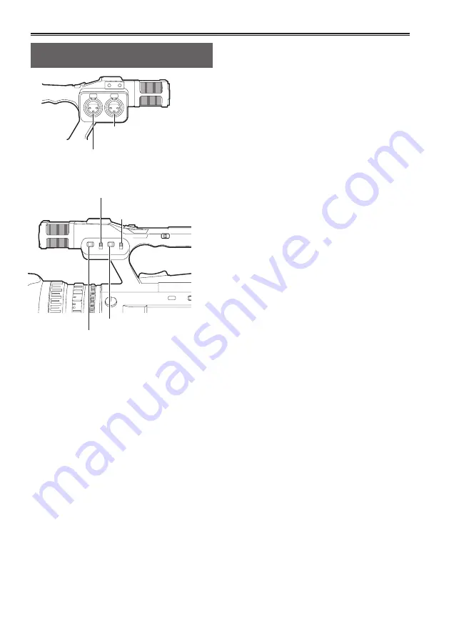
Using an external microphone and 

audio devices

INPUT1 switch

(MIC POWER +48V)

INPUT2 switch

(MIC POWER +48V)

INPUT1 LINE/MIC switch

INPUT2 LINE/MIC switch

AUDIO INPUT1 terminal

(XLR 3-pin)

AUDIO INPUT2 terminal

(XLR 3-pin)

Connect an external microphone or audio 

device to the AUDIO INPUT1/2 terminals (XLR 

3-pin). (Page 67)

Switch the connected audio input signal 

with the INPUT1 LINE/MIC switch or INPUT2 

LINE/MIC switch.

<LINE>: (When connecting audio device)

The input level is 0 dBu.

<MIC>: (When connecting an external 

microphone)

The factory setting for input level is -50 dBu.
The input level can be changed to [-40dB] or 
[-60dB] with the [MIC GAIN1] item and [MIC 
GAIN2] item on the setup menu [RECORDING 
SETUP] screen. (Page 90) However, sensitivity 
will be higher when set to [-60dB], and more 
noise may be recorded.

When using the phantom microphone (which 

re48V power supply)

Set the INPUT1 switch (MIC POWER+48V) and 
INPUT2 switch (MIC POWER+48V) to <ON>.

<ON>: (When connecting the phantom 

microphone)

+48V power is supplied to AUDIO INPUT1/2 
terminals.

<OFF>: (When not connecting the phantom 

microphone)

+48V power is not supplied to AUDIO 
INPUT1/2 terminals.


When you use a phantom microphone, the 
battery duration will become shorter.


When devices that do not s48V 
power supply are connected, set the phantom 
microphone to <OFF>. If set to <ON>, the 
connected devices might be damaged.


When using the AG-MC200G (optional), set 
the [MIC GAIN1] or [MIC GAIN2] item of the 
[RECORDING SETUP] screen to [-50dB].

Use the AUDIO CH1 SELECT switch to select 

the input signal to be recorded to audio 

channel 1.

<INT (L)>:

Audio from the built-in microphone Lch is 
recorded.

<INPUT1>:

Audio from the device connected to AUDIO 
INPUT1 terminal is recorded.

<INPUT2>:

Audio from the device connected to AUDIO 
INPUT2 terminal is recorded.

Use the AUDIO CH2 SELECT switch to select 

the input signal to be recorded to audio 

channel 2.

<INT (R)>:

Audio from the built-in microphone Rch is 
recorded.

<INPUT2>:

Audio from the device connected to AUDIO 
INPUT2 terminal is recorded.

Summary of Contents for AVCCAM AG-AC160EJ

Page 1: ...Card Camera Recorder Before operating this product please read the instructions carefully and save this manual for future use Volume 2 Note that Operation Instructions Vol 2 describes advanced operations of the Memory Card Camera Recorder For instructions on basic operations of the Memory Card Camera Recorder refer to Operating Instructions Vol 1 printed documents contained in the supplied CD ROM ...

Page 2: ... left and right 8 Tally lamp 9 Basic shooting operations 10 Preparing for shooting 10 Shooting in Auto mode 11 Checking recorded images REC CHECK 12 Memory card access lamp 12 Selecting a slot 12 Formatting memory cards 13 Memory card recording times 14 Removing memory cards 15 Protecting memory cards 15 Repairing memory cards 16 Using the zoom function 17 Digital zoom function 17 Shooting in manu...

Page 3: ... the built in battery setting the time code 51 Charging the built in battery 51 Setting the time code 51 Specifying the time code TC PRESET item 51 Setting user information 53 Playback Basic playback operations 54 Thumbnail screen 55 Basic thumbnail screen operations 55 Adding shot marks to clips 57 Selecting the memory card slot for playback 57 Playback settings PLAY SETUP 58 Setting playback for...

Page 4: ...ETUP screen 91 AV OUT SETUP screen 92 DISPLAY SETUP screen 93 CARD FUNCTIONS screen 96 USER FILE screen 96 META DATA screen AVCHD mode only 97 OTHER FUNCTIONS screen 97 OPTION MENU screen 99 PLAY SETUP screen 99 THUMBNAIL screen 100 OPERATION screen 100 Reference Before calling for service 101 Updating the firmware incorporated into the unit 105 Cleaning 106 Storage precautions 106 Recording forma...

Page 5: ...iewfinder can be raised to about 90 perpendicular to the camera 3 Adjust the diopter adjustment dial so that you can see the characters on the finder screen clearly Diopter adjustment dial Viewfinder Do not leave the eyepiece of the viewfinder pointed in the direction of the sun or strong light sources Internal components may be damaged or fire may be caused if light is focused through the lens Wh...

Page 6: ...osed Operation status displays when shooting a self portrait No display You cannot record no memory card etc Shooting in progress during transition to shooting pause Shooting paused shooting standby Warning display in progress Emphasizing image outlines Emphasizing the outlines of images in the viewfinder or the LCD monitor makes it easier to focus Emphasizing outlines does not affect recorded ima...

Page 7: ...lect YES in the EVF SET item on the setup menu DISPLAY SETUP screen LCD monitor adjustments Select YES in the LCD SET item on the setup menu DISPLAY SETUP screen 4 Select desired items by tilting the OPERATION lever in the or directions and push the OPERATION lever 5 Adjust the selected item by tilting the OPERATION lever in the or direction 6 Press the MENU button to release menu mode Color or mo...

Page 8: ... right By flipping the images displayed on the LCD monitor up down left and right the angle of view and imagery of images can be checked Even when the displayed image is flipped the recorded image is not flipped 1 Select LCD REV in the LCD item on the setup menu SW MODE screen LCD REV is assigned to the LCD button 2 Press the LCD button Pressing the button switches between normal display and flipp...

Page 9: ...lash when the camera is in any of the following circumstances When a recording error has occurred flashes 4 times per second When the battery has run out flashes 4 times per second When available memory card capacity is low flashes 4 times per second When battery level is low flashes once per second When remaining memory of the memory card is low flashes once per second Tally lamp ...

Page 10: ...D monitor remove the memory card and reinsert it Images shot from the start of shooting until it is stopped are recorded as one clip When recording is paused after a short recording time may be required after pressing the START STOP button before writing to the memory card is completed This means that if the START STOP button is pressed operations cannot be accepted immediately The camera reads in...

Page 11: ...appropriate level When FACE DETECT is set appears on the screen High priority frames with orange borders appear on the faces that are large or near the center and gray frames appear on the others Up to 15 detected frames are displayed on the screen If PRIMARY is set in the FACE FRAMING item of the setting menu SW MODE screen only the high priority orange frames are displayed The FACE DETECT functi...

Page 12: ...k with SIMUL REC Memory card access lamp Illuminated orange Reading writing possible Flashing orange slow Accessing memory card Flashing green Memory card write protected the slot with CHECK CARD indication no space left on memory card Illuminated green Other than the selected slot Off No memory card inserted unformatted memory card or incompatible memory card inserted When the USB is connected Fl...

Page 13: ...on to close the menu display 4 Select YES on the confirmation screen The memory card will be formatted 5 Press the MENU button to finish When a memory card is formatted all data including video images recorded on the memory card will be erased and cannot be restored Save important data to your computer When you use a memory card that has been formatted in DV mode in AVCHD mode only the system form...

Page 14: ...ory card of SD speed class 4 or above when recording with PH mode HA mode Recording cannot be performed with a memory card of lower than SD speed class 4 2 Use a memory card of SD speed class 2 or above when recording with PM mode HE mode 3 This is the highest quality mode of the camera The camera utilizes the VBR recording system VBR stands for Variable Bit Rate a recording system where the bit r...

Page 15: ...separate clip Saved data can be manipulated as a single clip during thumbnail operation of the camera When handled with nonlinear editing software or a computer clips are handled as the separate clips Removing memory cards 1 Slide the OPEN lever of the memory card slot cover down to open the cover Ensure that the memory card access lamp is not flashing orange before opening the cover 2 Press the c...

Page 16: ...displayed after inserting a memory card which has no error but repair will not be performed even when YES or NO is selected Repair may take up to approximately 20 minutes depending on the places where the errors occurred on the memory card Use a battery with an adequate charge or the AC adaptor If the repair operation has failed SYSTEM ERROR TURN POWER OFF will be displayed In this case use the AV...

Page 17: ...n using the FUNCTION knob is activated Page 26 Using the zoom function This camera is equipped with 22 power optical zoom Operate zoom with either the zoom lever or the zoom ring Zoom lever When the ZOOM switch is put in the SERVO position zoom can be operated with the zoom lever by means of motor drive T Zoom in W Zoom out Push the zoom lever on the hand strap lightly to zoom slowly and push it s...

Page 18: ... auto focus mode and the focus can be set automatically Switching to manual focus assist mode You can switch from manual mode to manual focus assist mode by turning ON the MF ASSIST item on the setup menu SW MODE screen Focus adjustment is performed roughly with about half the work in focus ring operation compared to the manual focus mode After adjustment with the focus ring focus adjusts automati...

Page 19: ...for the status of the light intensity See page 79 regarding IRIS METER display Regarding the F values when the lens aperture is open on this camera F1 6 is the wide angle side W end and F3 2 is the telescopic side T end In the iris display displayed on the viewfinder and the LCD monitor when the lens aperture is open OPEN is displayed on the wide angle side W end and F3 2 or OPEN is displayed on t...

Page 20: ... AUTO SW screen auto gain is on during auto mode regardless of the position of the GAIN switch Page 88 When the recording frame rate is 2 fps 0 dB is fixed regardless of the position of the GAIN switch Light intensity adjustment When natural light is strong use the ND FILTER dial to switch the ND filter light intensity adjustment filter to use OFF ND filter is not used 1 4 Intensity of light is cu...

Page 21: ...uring auto mode Page 88 When the following error messages are displayed try to adjust white balance again after performing remedies Error message Adjustment method LOW LIGHT Increase light intensity Or raise the gain LEVEL OVER Decrease light intensity Or lower the gain When the error messages are displayed after repeated attempts consult your dealer Using preset values This is convenient when the...

Page 22: ...e balance Message during adjustment ABB ACTIVE Message when adjustment is completed ABB END Even when the ATW function is in use continue to press the AWB button to adjust black balance Black balance cannot be adjusted during shooting ATW Auto Tracking White function The ATW function automatically decides the shooting environment and always automatically adjusts for optimal white balance during sh...

Page 23: ...r output and recording of video signal the 24 frames second image is converted with a general 2 3 conversion method to 60 field per second interlace signal This mode gives video with a movie feeling A B C D E F G H AoAeBoBeBoCeCoDeDoDeEoEeFoFeFoGe GoHeHo He 24 P 60 i 25P mode Shoots 25 frames second in the progressive mode For output and recording of video signal the 25 frames second image is conv...

Page 24: ...n shoot yourself like looking in the mirror However even though shooting in mirror mode the recorded images are the same as normal shooting Images are not recorded as mirrored images When you press the REC CHECK button images are not played back in right and left flipped state Operation status displays when shooting a self portrait No display You cannot record no memory card etc Shooting in progre...

Page 25: ...ge 25 to display the marker in the center of the screen You can check brightness near screen center as a number 0 99 When brightness exceeds 99 99 is displayed 99 Image level detection area Image level Marker Press the ZEBRA button again to return to the normal screen Checking and displaying shooting status DISP MODE CHK button Hold down the DISP MODE CHK button during shooting standby or shooting...

Page 26: ...ENU setting FOCUS Y GET Simultaneous operation of area focus function and area luminance display simultaneous operation of area focus bar function during MENU setting 2 Press the FUNCTION knob A white frame is displayed There is no change in the operation of the camera other than the display of the frame 3 Press the FUNCTION knob again The white frame turns yellow When the frame is yellow the FUNC...

Page 27: ...io fades out in the same way Also continue to press the button and the image fades out release the button and it fades in Using USER buttons You can assign a single function from among 16 types of functions to each USER button Use these buttons to change shooting conditions quickly or add the fade effect to images to match the subject In the factory settings the following functions are assigned to...

Page 28: ...ot displayed in external output LETTER BOX Recording is performed in 16 9 angular field The black band at the top and bottom of the screen is recorded When set to LETTER BOX images are displayed in a 16 9 aspect ratio and LT BOX is displayed on the LCD and viewfinder SQUEEZE The camera image is recorded compressed in the horizontal direction When recorded images are played on a wide screen support...

Page 29: ...mage points in a clip while shooting or playing back When the USER button assigned to the INDEX function is pressed during shooting an index signal is recorded at that point Page 87 It is also possible to add indexes during playback or to display play back only clips with indexes Page 60 A maximum 100 indexes can be recorded to a single clip When exceeding 100 indexes even though the attachment op...

Page 30: ...s been set and 24 25 frames form a one second video You can specify the interval in CAMERA mode with the INTERVAL REC item in the setting menu RECORD SETUP screen 1SECOND 10SECONDS 30SECONDS 1MINUTE 2MINUTES Changes the INTERVAL REC setting OFF Does not set the INTERVAL REC appears on the display INTERVAL REC setting will be released when shooting is finished Audio recording is disabled The PRE RE...

Page 31: ...ME item on the DISPLAY SETUP screen If this item is set to OFF the date and time will not be recorded as a time stamp To avoid date and time displays overlapping when clips with timestamps recorded are played with this camera set the DATE TIME item on the DISPLAY SETUP screen to OFF You can also hide the date and time display by pressing the DISP MODE CHK button Relay function When the remaining s...

Page 32: ...ing memory becomes full SIMUL REC will stop This figure shows the case that the memory card in Slot 1 becomes full Start recording End recording Start recording Clip C Stop recording memory full Memory card recording time Standby Standby SIMUL REC cannot be used at the same time as relay recording VFR recording or INTERVAL REC During SIMUL REC if recording has stopped because a recording error has...

Page 33: ...verwriting to the media in the external device Backup recording may not work properly if two or more external devices are connected Use an IEEE1394 cable that is 4 5 m or shorter When performing backup recording set the external device so that it records 1394 signals If you perform backup recording with CHAIN in the DV CONTROL item Page 97 of the setting menu OTHER FUNCTIONS screen set to on when ...

Page 34: ...cess lamp is not flashing 24P mode Shoots 24 frames second in the native mode A 24 frames second image is recorded into 24 frames as video signal 1 2 3 4 1 1 1 2 2 3 3 3 4 4 1 1 2 3 4 2 3 4 Camera 24P 24P native Valid frames The recording frame rate can be set to any one from the 23 frame rates given in the following table There is a slight difference between the displayed recording frame rate and...

Page 35: ...rd access lamp is not flashing Standard recording 1 Select the recording format PH 1080 30P 1 or PH 1080 25P 2 in the REC FORMAT item on the setup menu RECORDING SETUP screen Page 89 2 Turn the VFR MODE item on the setup menu SCENE FILE screen ON and set an optional recording frame rate in the FRAME RATE item Page 83 3 Press the START STOP button Standard recording starts in VFR mode When VFR mode...

Page 36: ...ulldown 30 fps PH 1080 25P 25 fps Undercrank shooting This is a quick motion effect that can be applied to scenes showing the flow of clouds people standing in the middle of crowds and kung fu etc For example a quick motion effect of x2 can be gained if the VFR recording frame rate is set to 12 fps when recording with the 24P recording format that specifies the playback frame rate Recording format...

Page 37: ...al operation Setting the shutter 1 Press the DIAL SEL button and select DIAL SHUTTER 2 Press the SHTR F RATE dial Each time the SHTR F RATE dial is pressed the shutter will turn ON OFF The shutter speed is changed in the order shown in the charts on page 39 by turning the SHTR F RATE dial when the shutter is ON Remember that the faster the shutter speed the lower the camera sensitivity Focusing on...

Page 38: ... setup menu SCENE FILE screen deg angle display 180 0d etc sec speed display 1 48 0 etc Setting the frame rate 1 Press the DIAL SEL button and select DIAL FRAME RATE 2 Press the SHTR F RATE dial Each time the SHTR F RATE dial is pressed VFR OFF and the frame rate setting mode switch The frame rate can be set by turning the SHTR F RATE dial The frame rate can also be set from the FRAME RATE item in...

Page 39: ...e setting If the shutter speed setting has been changed it is displayed in brackets like 1 25 AVCHD mode when VFR MODE OFF DV mode SYSTEM FREQ 59 94Hz When 1080 60i 720 60P 480 60i Normal OFF 1 60 SYNCHRO SCAN 1 30 1 2000 1 1000 1 500 1 250 1 120 1 8 1 15 1 100 When 1080 30P 720 30P 480 30P Normal OFF 1 50 SYNCHRO SCAN 1 30 1 2000 1 1000 1 500 1 250 1 120 1 8 1 15 1 60 When 1080 24P 720 24P 480 24...

Page 40: ...ching to progressive mode you can also shoot the PAL system television screens If the set value of the SYNCHRO SCAN item on the setup menu SCENE FILE screen is displayed in gray it cannot be used with the current recording format This function will only operate for preset values for each recording format The preset values for each recording format are as follows SYNC SCAN TYPE sec 60i 60P mode 1 6...

Page 41: ...ilt in microphone external microphone or connected audio devices AUDIO CH1 SELECT switch AUDIO CH2 SELECT switch Using the built in microphone 1 Set the AUDIO CH1 SELECT switch to INT L Audio from the built in microphone Lch is recorded to audio channel 1 2 Set the AUDIO CH2 SELECT switch to INT R Audio from the built in microphone Rch is recorded to audio channel 2 ...

Page 42: ...d INPUT2 switch MIC POWER 48V to ON ON When connecting the phantom microphone 48V power is supplied to AUDIO INPUT1 2 terminals OFF When not connecting the phantom microphone 48V power is not supplied to AUDIO INPUT1 2 terminals When you use a phantom microphone the battery duration will become shorter When devices that do not support 48V power supply are connected set the phantom microphone to OF...

Page 43: ...parately When AUTO is set the recording level adjustment using the AUDIO LEVEL knob and the setting in the AUDIO LIMITER CH1 AUDIO LIMITER CH2 item of the setup menu RECORDING SETUP screen Page 90 are disabled Since the audio signal recording level is adjusted automatically the zoom operation sound may be recorded if zooming quickly depending on the environment Adjusting the audio recording level ...

Page 44: ... SETUP screen See page 89 F6 SCENE CINE D File suitable for shooting movie like scenes where dynamic range is emphasized Even when the scene file is changed the recording format is unchanged It must be set with the REC FORMAT item on the RECORDING SETUP screen See page 89 Changing scene file settings The setting value of a scene file can be changed Also changed scene files can be stored at each po...

Page 45: ...When setting the file name press the RESET TC SET button to clear the characters 7 When finished setting the file name push the OPERATION lever 8 Select YES on the confirmation screen When you select YES you will exit the NAME EDIT screen and the setting change completes Once the setting change has been completed the changed name and values are stored and they remain after turning off the power or...

Page 46: ...e camera ON Page 30 of Vol 1 2 Select the slot number for the memory card onto which you wish to save from the CARD WRITE item on the setup menu SCENE FILE screen and push the OPERATION lever For other settings select the USER FILE screen Page 96 Menu operation Page 31 of Vol 1 Operations may be performed with buttons on the remote control that correspond to those on the camera For details see Rem...

Page 47: ... To add titles to files 1 Go through steps 1 to 3 2 Tilt the OPERATION lever in the directions to select a character and tilt in the direction to move to the next character The following characters can be input Space A Z 0 9 _ 3 When all input is finished push the OPERATION lever 4 Press YES on the confirmation screen If WRITE PROTECT appears release the protected status of the memory card If FILE...

Page 48: ...quipment model name AG AC160 for this camera CLIP PROPERTY SHOOT This indicates the SHOOTER name of the videographer and the PLACE NAME name of shooting location CLIP PROPERTY LOCATION This indicates ALTITUDE LONGITUDE LATITUDE of the shooting location and SOURCE information source Not recorded in this camera CLIP PROPERTY SCENARIO 2 This indicates the PROGRAM NAME SCENE NO scene number and TAKE N...

Page 49: ...re used in the metadata file to be loaded they are displayed as RECORD Sets whether to record the metadata loaded on the camera simultaneously on a memory card when recording Select either ON OFF format do not format and push the OPERATION lever The factory setting for this mode is OFF USER CLIP NAME The USER CLIP NAME recording method is selectable For details see the next column META DATA PROP D...

Page 50: ...n No display Data is not displayed To reset the counter value press the RESET TC SET button while the counter value is being displayed TC preset mode Synchronizes the initial time code value during multi camera shooting Hereafter the camera used for synchronization is described as the MASTER and the camera being synchronized is described as the SLAVE 1 Connect the TC PRESET IN OUT terminals VIDEO ...

Page 51: ...and time are not remembered after charging the built in battery needs to be replaced Consult your dealer Setting the time code Perform various time code related settings with the following items on the setup menu TC UB SETUP screen Page 91 TC MODE item TCG item TC PRESET item UB MODE item DV mode only Specifying the time code TC PRESET item Set the time code value with the TC PRESET item to record...

Page 52: ...hed setting the time code value push the OPERATION lever 6 Tilt the OPERATION lever in the direction to move to YES and push the OPERATION lever This camera adjusts the time code value in accordance with the format and frame rate For this reason bear in mind that making a change in the format or frame rate may result in discontinuity from the last time code value of the previous recording Adjustme...

Page 53: ...ns on the remote control that correspond to those on the camera For details see Remote control Page 24 of Vol 1 3 Tilt the OPERATION lever in the direction to move to YES and push the OPERATION lever 4 Set the user information Tilt the OPERATION lever in the directions to select user information characters You can set numbers from 0 to 9 and letters from A to F for the user information Tilt the OP...

Page 54: ...speed through the clip Repeat the operation to scroll more quickly backwards approx 20 times the speed Press while pause to move to the previous clip ZOOM START STOP PHOTO SHOT EXT DISPLAY DATE TIME VOL PLAY STOP SKIP SKIP MENU ENTER PAUSE SEARCH STILL ADV STILL ADV SEARCH Stop ZOOM START STOP PHOTO SHOT EXT DISPLAY DATE TIME VOL PLAY STOP SKIP SKIP MENU ENTER PAUSE SEARCH STILL ADV STILL ADV SEAR...

Page 55: ...in thumbnails in AVCHD mode When two memory cards containing clips are inserted in both memory card slots clips in the memory card in the selected slot will be displayed in thumbnails To display the thumbnails of clips in another memory card switch the slot for playback Page 57 If a memory card includes more than 1000 clips thumbnails exceeding 1000 will not be displayed To display clip informatio...

Page 56: ... a time code at start of clip recording user information at start of clip recording shooting time shooting date shooting date and time according to settings 8 Recording format display Displays recording format of the clip with the cursor position 9 Duration display Displays duration of the clip with the cursor position 10 Clip number Displayed in order of shooting Up to 1000 clips Numbers of clips...

Page 57: ...ete clip When the recording capacity of one clip exceeds 4 GB recording time is approximately 16 minutes the clip is automatically split and saved as another clip This is displayed on clips that were not saved successfully as associated clips due to power being switched off during recording etc To display CLIP PROPERTY on the thumbnail screen move the cursor using the OPERATION lever to the clip y...

Page 58: ...etup menu RECORDING SETUP screen is restored when the camera is switched to CAMERA mode If the playback format does not conform to the clips created at the relay destination using the relay recording function thumbnail images will not be displayed will be displayed Thumbnail images will be displayed when the playback format is matched to the clips Repeat playback REPEAT PLAY Use this setting to re...

Page 59: ...u turn OFF the power or switch to CAMERA mode the video position that was being played is canceled Playback will start from the beginning of the last clip Setting the skip method SKIP MODE only in AVCHD mode Select which skip cue operation is to be performed when playback is paused 1 Press the MENU button Menu operation Page 31 of Vol 1 2 Select the SKIP MODE item in the PLAY SETUP screen 3 Select...

Page 60: ...n the same format as the current PB format MARKER Displays all clips with shot marks INDEX only in AVCHD mode Displays all clips with indexes INDICATOR Sets ON OFF display hide of indicator Factory setting is ON Clip protect display and resume playback display will still appear even if this setting is set to OFF DATA DISPLAY Select format of clip time display TC time code UB user information TIME ...

Page 61: ...tion to select multiple clips Press the EXEC button to confirm tilt the OPERATION lever in the directions to select YES NO delete do not delete and push the OPERATION lever NO Returns to the previous screen Protected clips cannot be deleted If selecting ALL CLIPS to delete all clips from the memory this operation may take some time to complete depending on the volume of clips to be deleted Deletio...

Page 62: ...be displayed Cancels protection when the protected clip is selected mark will disappear Formatting the memory card will delete all clips even if they are protected NO Returns to the previous screen 4 Press the MENU button to return to the thumbnail screen Repairing clips only in DV mode Repair clips on which the defective clip indicator X Yellow is displayed on the thumbnail screen Clips with the ...

Page 63: ...N lever CARD FORMAT Insert a memory card to be formatted into the camera When a memory card is formatted all data including clips shot in AVCHD mode and DV mode is erased and cannot be restored Save any valuable data on your computer before formatting Select YES NO format do not format and push the OPERATION lever CARD STATUS Displays the memory card information Page 64 CLIP PROPERTY Displays info...

Page 64: ...ART UB User information value at start of recording DATE TIME Date of recording and time at start of recording TIME ZONE Displays time zone DURATION Clip length FORMAT Recording format Clip metadata AVCHD mode only Press the EXEC button while the clip information screen is being displayed to display more detailed information including video and audio formats and information about the videographer ...

Page 65: ...ay or press the PLAY button on the remote control The screen will return to the thumbnail display after the playback of the last clip is completed during fast forward playback The screen will pause at the first clip after the fast rewind playback of the first clip is completed No audio will be played during fast forward or rewind playback Next previous clip 1 Tilt the OPERATION lever in the direct...

Page 66: ...adjusted with the AUDIO MON ADV buttons during playback Press the ZOOM VOL buttons if using the remote control ZOOM DATE TIME VOL Camera or remote control Viewing images on a television or another monitor You can view the images on a television if you connect the unit to a television or another monitor set using a video pin cable optional audio pin cable optional HDMI cable optional or BNC cable o...

Page 67: ...holder Microphone holder adaptor 12 mm 6 mm When attaching an external microphone to the microphone shoe use the supplied microphone holder and microphone holder adaptor When attaching the microphone holder and the microphone holder adaptor be sure to tighten the screws firmly even though you might hear a squeaking sound When wiring the microphone cable use the cable clamper of the microphone hold...

Page 68: ...ing an IEEE1394 cable optional and perform 1394 AVC transfer Only in DV mode Set the camera to the PB mode IEEE1394 cable optional Computer 6 pin When controlling the camera from a nonlinear editing device you can operate the clip on the cursor position in the thumbnail screen which is displayed on the LCD When the camera cannot be controlled by the nonlinear editing device operate the clip to imp...

Page 69: ... be sure to turn off the power of the device to be connected When connecting an external device equipped with a 4 pin type IEEE1394 terminal connect the DV OUT terminal 6 pin first Use a double shielded IEEE1394 cable AUTO REC function You can output the information on start stop of the recording via the SDI HD output when recording with the camera starts stops and control an external device You c...

Page 70: ...ptional with double shield that is equivalent to 5C FB to connect to SDI OUT terminal Limitations of image output When using SDI OUT output the LCD monitor and the viewfinder cannot be displayed simultaneously In order to display them simultaneously set the SDI OUT item on the setup menu AV OUT SETUP screen to OFF When the EVF MODE item on the setup menu DISPLAY SETUP screen is set to AUTO the vie...

Page 71: ...Hz Mode Menu settings Output terminal format REC FORMAT SDI HDMI OUT SEL DOWNCON MODE SDI OUT SDI OUT HDMI OUT VIDEO OUT DV OUT AVCHD 1080 50i 25P 1080i 720P Menu settings disabled ON 1080 50i 1080 50i No output No output 720 50P 25P 1080 50i 1080 50i No output 1080 50i 25P SIDE CROP LETTER BOX SQUEEZE 1 OFF No output 1080 50i 576 50i 720 50P 25P No output 720 50P 576 50i 3 1080 50i 25P 720 50P 25...

Page 72: ...ying files from the camera to a computer take care to ensure that files are not accidentally overwritten For more details refer to the operating instructions of your computer editing software When changing memory cards always ensure that the access lamp is not flashing and that the memory card is not currently being accessed Camera functions cannot be used when the camera is connected to a compute...

Page 73: ... metadata supported by the camera is held in a special manufacturer area in the control file area for the AVCHD standard If files are deleted or copied if clip protection is added or removed or if other such editing operations have been performed using editing software or a camera recorder which does not support this camera s metadata the special area for the metadata will be erased and the shot m...

Page 74: ...y Disc read the operating instructions of the Blu ray Disc Recorder When dubbing of videos shot with the camera is performed on a Blu ray Disc BD RE BD R HDD or DVD metadata information supported by the camera will be lost In order to perform dubbing including metadata information use the dedicated software AVCCAM viewer Page 73 1 Remove the memory card from the camera after shooting Turn the powe...

Page 75: ...n a time code value has not been correctly read from the memory card TC is displayed UB User information value When a user information value has not been correctly read from the memory card UB is displayed Normal displays During AVCHD mode STD ATW AREA 60 1 2 ALCH1 2 META R123 h45m 1h12m 99 1 1000 15dB ND1 64 D5X 14 LPCM 1 12 13 14 15 16 17 18 19 29 28 27 26 25 24 4 5 3 23 22 21 20 30 31 32 33 34 ...

Page 76: ...ayed when you switch the AUTO MANU switch to MANU When shooting in manual mode that allows FACE DETECT function when setting auto focus or auto iris 8 Operation status display Red Shooting Green Shooting paused Green Playback White Playback paused INDEX Playback paused at INDEX position Frame by frame playback Frame by frame reverse playback Cued playback cued reverse playback Fast forward fast fo...

Page 77: ...h is set to MANU and the AUDIO LIMITER CH1 AUDIO LIMITER CH2 items on the setup menu RECORDING SETUP screen are ON AL CH 1 When AUDIO LIMITER CH1 ON AL CH 2 When AUDIO LIMITER CH2 ON ALCH1 2 When AUDIO LIMITER CH1 AUDIO LIMITER CH2 ON 19 Recording audio type display AVCHD mode only LPCM During LINEAR PCM recording In VFR recording an indication appears to show that audio is not recorded Audio is n...

Page 78: ...en the MF ASSIST item on the setup menu SW MODE screen is set to ON MA appears in the manual focus mode When the macro control is set AF MF or MA is displayed in black white reverse 95 Focus distance infinity 00 Focus distance approximately 5 cm Depending on the zoom position it may not be within the macro range Also the lower limit of the macro range may differ depending on the zoom position The ...

Page 79: ...compensation 34 IRIS METER display Displays the preceding bar in the bottom right of the LCD monitor viewfinder Center Indicates the normal light intensity Right Indicates high light intensity Left Indicates low light intensity Green dots on display Indicate the compensation amount during AUTO IRIS 35 Iris display Displays F value 36 Shutter speed display Displays the shutter speed 37 Monitor audi...

Page 80: ...W PRE REC cannot be set because the remaining memory card capacity is low CARD DOOR OPENED The memory card door is open CARD ERROR PLEASE REFORMAT Formatting has failed This memory card needs to be reformatted CARD FULL The memory card is full CHECK CARD Please check the memory card If a memory card that has been used before in another device or computer is used for the first time in this camera C...

Page 81: ...error has occurred in the camera or the memory card If the problem is not solved by switching the power off and back on again either change the memory card in accordance with the instructions displayed or consult your dealer E ERROR OCCURRED PLEASE TURN POWER OFF Displayed when an error has occurred on the camera Turn off the power R REC WARNING Displayed when an error has occurred during recordin...

Page 82: ...tical image stabilizer display 3 3 3 3 x 22 Scene file name display 3 3 3 x x 23 AWB information display 3 3 3 3 2 x 24 Gain display 3 3 3 3 3 x 25 ND filter display 3 3 3 x x 26 Date and time display 3 3 4 27 Focus control information display 3 3 28 Zoom position display 3 3 29 FOCUS BAR display 3 3 30 Information display 3 31 Time stamp display 3 3 32 Audio level meter display 3 3 33 Auto iris c...

Page 83: ...F RATE on the left side of the camera body When SYSTEM FREQ 59 94Hz When REC FORMAT PH 1080 24P PH 1080 30P 2 6 9 12 15 18 20 21 22 24 25 26 27 28 30 32 34 36 40 44 48 54 60 When SYSTEM FREQ 50Hz When REC FORMAT PH 1080 25P 2 6 9 12 15 18 20 21 22 23 24 25 26 27 28 30 32 34 37 42 45 48 50 SYNC SCAN TYPE CAMERA Selects the synchro scan display setting deg Sets to angle display sec Sets to speed dis...

Page 84: ...ne adjustments to the color temperature after white balance Bch adjustment 7 0 7 MASTER PED CAMERA Adjusts the master pedestal black level of the image as the basis for images 15 0 15 A IRIS LEVEL CAMERA Sets the desired AUTO IRIS level 6 0 6 DRS CAMERA Selects the DRS dynamic range stretcher function ON Enables the DRS function OFF Disables the DRS function If you assign the DRS function to the U...

Page 85: ...on starts at approx 90 HIGH High setting Compression starts at approx 100 Not available when a DRS value is set or when GAMMA is set to CINE LIKE MATRIX CAMERA Selects the MATRIX table suitable for the desired color expression during shooting NORM1 Suitable for shooting in the open air or under a halogen lamp NORM2 Suitable for brighter colors than the NORM1 mode FLUO Suitable for shooting under f...

Page 86: ...ite function on the WHITE BAL switch on the position A B or PRST When the ATW function is assigned to the USER button the USER button operation remains effective Ach Activates the ATW function when the WHITE BAL switch is set to A Bch Activates the ATW function when the WHITE BAL switch is set to B PRST Activates the ATW function when the WHITE BAL switch is set to PRST OFF Deactivates the ATW fun...

Page 87: ...ark Page 29 Enabled during recording thumbnail display and clip display INDEX Enabled during index recording Page 29 AVCHD only LAST CLIP Deletes the last recorded clip Page 29 You cannot delete clips if the following operations are performed after shooting When switched to PB mode When changing the recording format When connecting to a computer using a USB cable When powering off the camera When ...

Page 88: ...hite balance value OFF Deactivates the ATW function when in Auto mode Activates white balance function selected using the WHITE BAL switch AF CAMERA ON Activates auto focus when in Auto mode At this time the FOCUS switch is disabled OFF Deactivates auto focus when in Auto mode Performs focus operation selected using FOCUS switch is the factory default mode Item Display mode Description of settings...

Page 89: ...NV CAMERA DV mode only Selects aspect ratio for DV mode recording SIDE CROP Records in 4 3 Crops the left and right edges LETTER BOX Records in 16 9 Adds black bands at the top and bottom of the screen SQUEEZE Records with horizontal compression of picture PREREC MODE CAMERA Sets the pre recording to ON or OFF ON Enables the pre rec function OFF Disables the pre rec function TCG is set to FREE RUN...

Page 90: ...ME item is superimposed OFF Date and time information are not superimposed on the image PH AUDIO MODE CAMERA AVCHD mode only Selects the format of audio recording when REC FORMAT PH LINEAR PCM Recording is performed in uncompressed LPCM Dolby Digital Recording is performed in Dolby Digital The camera is fixed to Dolby Digital other than PH mode Content recorded with LINEAR PCM cannot be played bac...

Page 91: ...o 0 or a multiple of 4 in AVCHD mode and to 5 frame units in DV mode If any other value is set the recorded time code will mismatch YES NO UB MODE CAMERA DV mode only Sets the content to be recorded as the user information USER Records the user information TIME The time is recorded DATE The date and time are recorded TCG Records the value of the time code generator FRAME RATE Records the frame rat...

Page 92: ...n the 1080 60i format When SYSTEM FREQ 50Hz this item is not available SDI EDH CAMERA PB Sets superimposition of EDH onto the SDI OUT during SDI OUT output ON Superimposes EDH OFF Does not superimpose EDH DOWNCON MODE CAMERA PB AVCHD mode only Switches down conversion output mode SIDE CROP Crops the left and right edges Images output from the external output terminals VIDEO OUT HDMI SDI OUT will h...

Page 93: ...AY SETUP screen Item Display mode Description of settings ZEBRA DETECT1 CAMERA Selects the brightness level of the right leaning zebra patterns on the screen 105 100 95 90 85 80 75 70 65 60 55 50 ZEBRA DETECT2 CAMERA Selects the brightness level of the left leaning zebra patterns on the screen OFF 105 100 95 90 85 80 75 70 65 60 55 50 Y GET MARKER CAMERA Sets the display of the marker used for dis...

Page 94: ...yed in PB mode VIDEO OUT OSD CAMERA PB Select ON to output the information displayed on the viewfinder or LCD monitor together with the signals from the VIDEO OUT jack ON OFF The external outputs VIDEO OUT SDI OUT HDMI include items that are not displayed DATE TIME CAMERA PB Sets whether to display the date and time on the viewfinder or LCD monitor and whether to output the date and time from the ...

Page 95: ...trast LCD BACKLIGHT CAMERA PB Adjusts the backlight of the LCD monitor 1 0 1 2 3 1 The backlight becomes brighter 3 The backlight becomes the darkest SELF SHOOT CAMERA Switches the LCD monitor to mirror mode for self portrait shooting Select MIRROR to flip the left and right side of the LCD monitor image during self portrait shooting NORMAL MIRROR EVF MODE CAMERA PB Switches the screen display of ...

Page 96: ... user files saved on the memory card SLOT1 Reads user files from the memory card inserted in slot 1 SLOT2 Reads user files from the memory card inserted in slot 2 NO Returns to the previous screen CARD WRITE CAMERA PB Saves user files on the memory card You can also add a title to the saved files SLOT1 Saves user file on the memory card inserted in slot 1 SLOT2 Saves user file on the memory card i...

Page 97: ...alue to 1 YES NO META INIT SET CAMERA AVCHD mode only Initializes the metadata recorded in the unit All settings including the ON OFF setting for RECORD are cleared YES NO is the factory default mode OTHER FUNCTIONS screen Item Display mode Description of settings IR REMOTE CAMERA PB Sets the operations of the supplied remote control unit ON Accepts commands from the remote control Note that if th...

Page 98: ...cago 06 30 07 00 Denver 07 30 08 00 Los Angeles 08 30 09 00 Alaska 09 30 Marquesas Islands 10 00 Hawaii 10 30 11 00 Midway Islands 11 30 12 00 Kwajalein Atoll 12 30 13 00 11 30 Norfolk Island 12 00 New Zealand 10 30 Lord Howe Island 11 00 Solomon Islands 09 30 Darwin Islands 10 00 Guam 08 30 09 00 Tokyo 07 30 08 00 Beijing 06 30 Yangong 07 00 Bangkok 05 30 Mumbai 06 00 Dacca 04 30 Kabul 05 00 Isla...

Page 99: ... is the factory default mode PLAY SETUP screen Item Display mode Description of settings PB FORMAT PB AVCHD mode only Sets the playback format When SYSTEM FREQ 59 94Hz 1080 60i 30P 1080 24P 720 60P 30P 720 24P When SYSTEM FREQ 50Hz 1080 50i 25P 720 50P 25P The REC FORMAT setting in the CAMERA mode prior to migrating to the PB mode becomes the default value of the PB FORMAT REPEAT PLAY PB ON OFF Wh...

Page 100: ...ATE TIME of the DATA DISPLAY item The factory setting values may vary depending on the region Y M D Year Month Day M D Y Month Day Year D M Y Day Month Year is the factory default mode OPERATION screen Item Display mode Description of settings DELETE PB Deletes clips ALL CLIPS Deletes all clips SELECT Deletes only the selected clips Press EXEC to delete NO Returns to the previous screen Clips for ...

Page 101: ... battery cannot be charged A DC cord may be connected to the AC adaptor The battery cannot be charged with the DC cord connected Page 24 of Vol 1 The remaining charge is not displayed correctly The remaining battery charge display is merely a guideline To ensure that remaining battery capacity is displayed correctly use the battery completely from a fully charged state and charge the battery again...

Page 102: ...s of your computer and connection cable P68 Cannot dub onto an external device Make sure the external device connected correctly P68 Displays Something is wrong with the time code display The time code display may not register a regular count if a clip is played back in the reverse slow mode but this is normal Playback Cannot play back content even when I press the play button Make sure the camera...

Page 103: ... initialization operation is performed when the camera starts up It occurs due to the construction of the camera and does not indicate a fault The memory card screen is abnormal The data on the memory card could be corrupted Data can be corrupted by static electricity and electromagnetic waves Always save important data to a computer or other storage media The memory card cannot be used even after...

Page 104: ...g the clip Mixture of different recording modes Recording format 1080 60i Playback format 1080 60i 30P Recording format PH 1080 60i Recording format Recording format HA 1080 60i HE 1080 60i Recording format HA 1080 60i The image pauses when switching the clip Some clips have been recorded using PRE REC function or VFR function Normal shooting PRE REC shooting VFR shooting PRE REC shooting VFR shoo...

Page 105: ...erence Updating the firmware incorporated into the unit To check the latest information on the firmware and update methods refer to the following support page on the Panasonic website http pro av panasonic net ...

Page 106: ...other places where the temperature is high Do not leave the memory cards where the humidity level is high or where there are high concentrations of dust Cleaning When cleaning do not use benzene or thinner Benzene or paint thinners may deform the camera body and or cause the surface finish to peel Before proceeding with maintenance remove the battery or disconnect the AC cord from the power outlet...

Page 107: ...24P Native recording PM 720 60P 720 60P HA 1080 60i 1080 60i HE 1080 60i 1080 60i DV 480 60i 480 60i 480 30P over 60i 480 24P over 60i When SYSTEM FREQ 50Hz Recording mode Frame rate 50i 25P AVCHD PH 1080 50i 1080 50i 1080 25P over 50i 720 50P 720 50P 720 25P over 50P PM 720 50P 720 50P HA 1080 50i 1080 50i HE 1080 50i 1080 50i DV 576 50i 576 50i 576 25P over 50i Recording format list ...

Page 108: ...ial 5 Dubbing 74 DV mode 14 30 11 E Error displays 81 Eye cup 29 F Firmware 105 Focus 18 Focus assist 19 Focus ring 18 G Gain 20 Gamma 85 H HDMI cable 70 HD mode 30 11 I IEEE1394 99 Index recording 29 INTERVAL REC 90 Iris 19 IRIS 19 L LAST CLIP 29 LCD monitor 17 6 Low angle shooting 24 M Manual focus 18 Manual mode 18 Memory card Access lamp 12 Format 13 Inserting 10 Protection 15 Recording data 7...

Page 109: ...ter speed 37 SIMUL REC 32 Specifications 38 Standard recording 35 Synchro scan 40 T Tally lamp 9 Thumbnail Display method 60 Thumbnail screen 55 Time code 51 U USB2 0 connection cable 68 USER button 27 User information 53 V Variable Frame Rate 34 36 VFR 34 36 Video pin cable 70 Viewfinder 5 W Warning 80 Wave form monitor function 28 White balance 20 Z Zebra patterns 25 ZOOM 17 Bold italic numbers ...

Page 110: ...2011 ...

Reviews: