


Operating Instructions
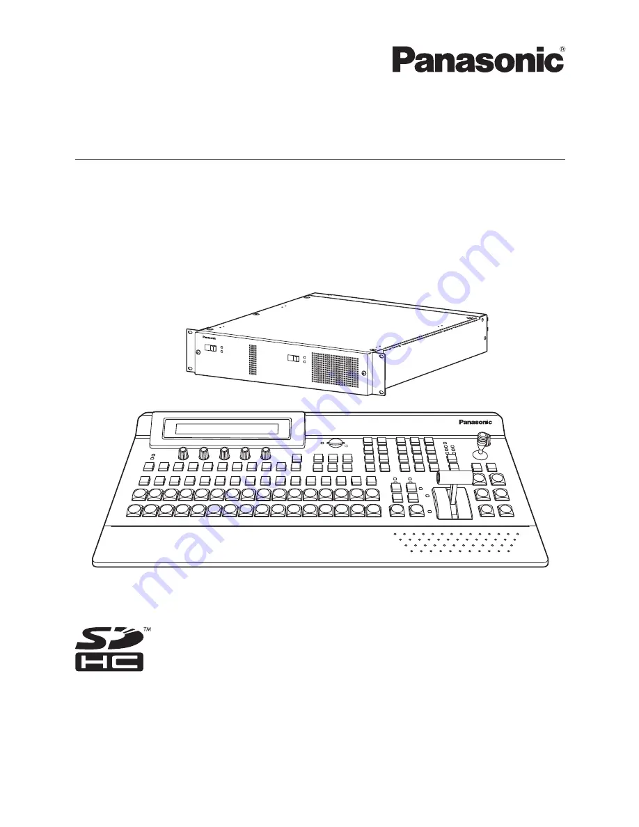
Multi-format Live Switcher
Model No.
AV-HS450N
Multi-format Live Switcher AV-HS450
POWER
ALARM
POWER1
POWER1
ALARM1
OFF
POWER2
ON
OFF
ON
POWER2
ALARM2
Multi-format Live Switcher A
V-HS450
Mainframe
[AV-HS450U1N]
Control panel [AV-HS450C1N]
Before operating this product, please read the instructions carefully and save this manual for
future use.
Printed in Japan
3TR006327AAC


