background image

– 170 –

Chapter 10 Menu Operations — Menu operations
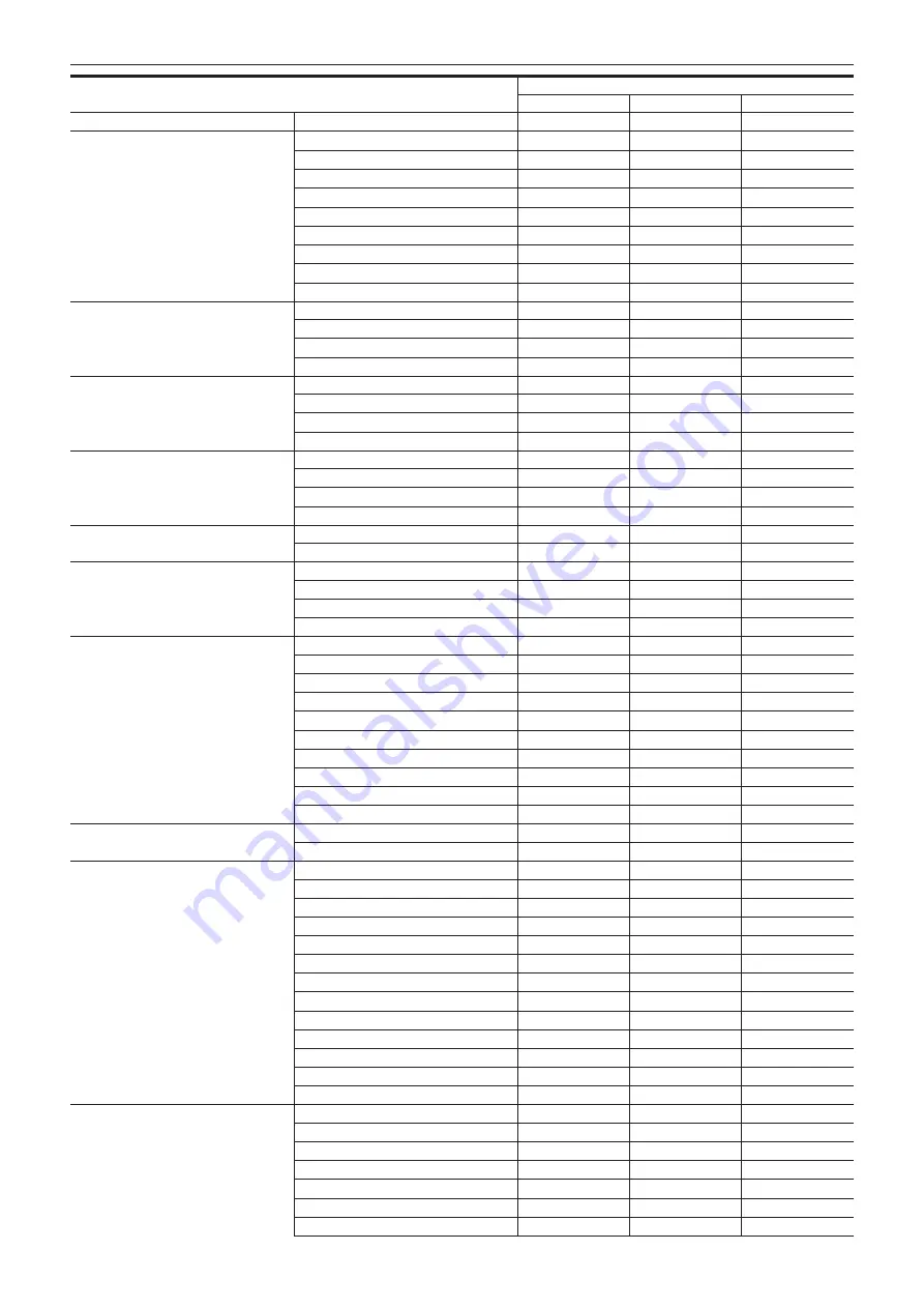
Item

Operation

UI

SW

VF

[ABB OFFSET]

[EI]

[MODE]

l

[ISO SELECT]

l

[NATIVE ISO]

l

l

l

[800BASE ISO]

l

l

l

[5000BASE ISO]

l

l

l

[GAIN MODE]

l

l

l

[GAIN SELECT]

l

l

l

[GAIN OFFSET SW]

[GAIN OFFSET LEVEL]

[GAMMA]

[GAMMA SELECT]

[MASTER GAMMA]

[R GAMMA]

[B GAMMA]

[BLACK GAMMA]

[SW]

[BLACK R GAMMA]

[BLACK MASTER GAMMA]

[BLACK B GAMMA]

[KNEE]

[KNEE SW]

[KNEE MODE]

[KNEE POINT]

[KNEE SLOPE]

[WHITE CLIP]

[SW]

[LEVEL]

[DETAIL]

[SW]

[CORING]

[MASTER LEVEL]

[FREQUENCY]

[SKIN DETAIL]

[SW]

[TABLE SELECT]

[GET]

[ZEBRA SW]

[EFFECT LEVEL]

[DETECT TABLE]

[- I CENTER]

[- I WIDTH]

[- Q WIDTH]

[- Q PHASE]

[CHROMA]

[LEVEL]

[PHASE]

[LINEAR MATRIX]

[SW]

[(R-G)_N]

[(R-G)_P]

[(R-B)_N]

[(R-B)_P]

[(G-R)_N]

[(G-R)_P]

[(G-B)_N]

[(G-B)_P]

[(B-R)_N]

[(B-R)_P]

[(B-G)_N]

[(B-G)_P]

[COLOR CORRECTION]

[SW]

[R (SAT)]

[R (PHASE)]

[P1(SAT)]

[P1(PHASE)]

[P2(SAT)]

[P2(PHASE)]

Summary of Contents for AU-V35LT1G

Page 1: ...LT Operating Guide Version 6 0 W0316HM6028 YI VQT5M58A 6 E The photograph is an example of a system ...

Page 2: ...mos Global Pty Ltd How to read this document r r Illustrations f f Illustrations may differ from the actual product r r Conventions used in this manual f f Words and phrases in brackets indicate details and content displayed in the viewfinder or control panel f f Words and phrases in brackets indicate design text used on this camera such as button names r r Reference pages f f Reference pages in t...

Page 3: ...g 37 File name style 38 Selecting the resolution codec and video format for recording 40 When FREQUENCY is set to 23 98p 40 When FREQUENCY is set to 24 00p 44 When FREQUENCY is set to 25 00p 46 When FREQUENCY is set to 29 97p 50 When FREQUENCY is set to 50 00p 54 When FREQUENCY is set to 59 94p 57 When FREQUENCY is set to 50 00i 61 When FREQUENCY is set to 59 94i 61 Color setting 62 COLOR screen s...

Page 4: ...T SETTINGS 154 FILE 160 PERIPHERAL 161 Initial value of the scene file 163 CAMERA SETTINGS 163 SCENE FILE SETTINGS 163 Menu operations 167 SYSTEM SETTINGS 167 CAMERA SETTINGS 169 SCENE FILE SETTINGS 169 REC SETTINGS 171 AUDIO SETTINGS 172 OUTPUT SETTINGS 173 FILE 175 PERIPHERAL 175 Target items for saving and initialization 177 SYSTEM SETTINGS 177 CAMERA SETTINGS 178 SCENE FILE SETTINGS 179 REC SE...

Page 5: ...Before using the camera read this chapter Chapter 1 Overview ...

Page 6: ...he sun Doing so might damage the components inside r r GPS GPS Global Position System satellite is managed by the United States Department of State and its precision is sometimes intentionally changed Position it in a location where there is a good view of the sky and there is no influence of obstacles such as roofs and trees etc Depending upon the surrounding environment and the time it may take ...

Page 7: ...cable f f Eye cup already attached to the electronic HD color view finder f f Eye piece filter already attached to the electronic HD color view finder Shoulder mount module optional AU VSHL2G f f Slide rail already attached to the shoulder mount module Grip module optional AU VGRP1G f f Grip arm already attached to the grip module PL lens mount module optional AU VMPL1G f f Mounting screw 2 pcs al...

Page 8: ...v panasonic net 2 Refer to the support desk at the following website for the latest information regarding the lens that can be used http pro av panasonic net 3 A battery holder is provided as standard on the camera 4 Refer to our support desk at the following website for the latest information not included in this document http pro av panasonic net Expansion system devices You can also use the fol...

Page 9: ...This chapter describes the names functions and operations of parts on the camera Chapter 2 Description of Parts ...

Page 10: ... will function as the menu selection dial when the menu is displayed by pressing the MENU button on the camera Volume level can be adjusted with this dial button by assigning DIRECT VOL CTRL to the USER button and calling the direct volume control function 10 Fan inlet Fan inlet for dissipating heat Do not block this when the camera is in use 11 TOGGLE WB switch WB EI SHUTTER can be assigned WB is...

Page 11: ...wfinder etc while the button with RETURN assigned is pressed The input signal is 3G HD SDI For the cable to connect to this terminal prepare a double shielded cable equivalent to 5C FB 6 TC IN OUT terminal Connects to the time code input terminal of the external device when locking the time code of the external device to the time code on the camera Inputs the standard time code when locking with t...

Page 12: ... For details refer to the Operating Instructions for the lens Cable for the grip module AU VGRP1G optional can also be connected Front 2 3 4 5 1 1 Accessory mounting holes For attaching accessories f f Mounting hole size 3 8 16 UNC screw length 5 5 mm or shorter 2 Lens cable clamp A clamp for securing the lens cable 3 EF lens mount EF lens is mounted 4 FILTER dial 1 CLEAR Does not use the ND filte...

Page 13: ... Top 1 2 5 5 6 1 4 3 1 Viewfinder mounting holes For attaching the viewfinder 2 Accessory mounting holes For attaching accessories f f Mounting hole size 1 4 20 UNC 3 8 16 UNC 3 GPS module position This part has a built in GPS module Do not hold the handle or block with an obstruction when GPS is in use 4 Microphone holder mounting position 5 Mounting hole for control panel mounting part 6 Accesso...

Page 14: ...nput terminal for 3G HD SDI video signal input Use the supplied BNC cable or the 5C FB equivalent double shielded cable for the cable to connect to this terminal 3 DC IN 12V terminal An input terminal for power supply input Connect to the electronic HD color view finder power supply terminal on the camera Use the supplied DC cable when connecting a cable to this terminal Using the external DC powe...

Page 15: ...ught close The eye sensor may not work properly depending on the shape of glasses in use how you hold the camera or the strong light hitting around the eye piece 2 Lock lever Secures the viewfinder in place 3 Eye piece filter Protective filter against dust water and moisture Use the camera with this attached 4 Stopper Used when removing the viewfinder from the slider unit Top 1 2 1 Lock lever left...

Page 16: ... the shoulder mount module Right side 2 1 3 1 Support rod lock knob Secures the rod in place 2 Accessory attachment rosette Attaches an accessory such as the dedicated grip module f f Mounting screw size M6 screw length 9 mm or shorter 3 Slide rail lock knob Secures the slide rail in place Front 1 1 Support rod mounting holes Holes for connecting a rod with a diameter of 15 mm Rear 1 1 Support rod...

Page 17: ...ned Pressing a button performs the assigned function 3 IRIS dial Controls the iris of the EF lens Sets the rotational direction of the dial and the control of the iris with the menu Volume level can be adjusted with this dial by assigning DIRECT VOL CTRL to the USER button and calling the direct volume control function Left side grip arm 2 1 1 Arm fixing knob Fixes after adjusting the length of th...

Page 18: ...ghtened using an Allen wrench Right side 2 1 1 Tightening hole The mount fixing ring can be tightened using an Allen wrench 2 Mounting screw The screw to fix the PL lens mount module to the camera Front 2 1 1 Lens fixing ring Fixes the lens by turning the ring after mounting the lens to the lens mount 2 Mount cap Attaches the cap when the lens is not mounted Rear 2 1 1 Contact Align with the conne...

Page 19: ...Attach the module following the procedure in this chapter before using The mounting of accessories is also described in this chapter Chapter 3 Preparation ...

Page 20: ...ol panel It can be mounted to the rear of the camera using the supplied dedicated mounting part Fig 1 Fig 3 Fig 4 Fig 2 CONTROL PANEL terminal 1 Mount the control panel mounting part using the four supplied screws Fig 1 2 Mount the control panel onto the control panel mounting part Fig 2 3 Push down the lock lever to the right to lock Fig 3 4 Connect the cable of the control panel to the CONTROL P...

Page 21: ...3 Push down the lock lever backwards to lock 4 Connect the BNC cable supplied with the viewfinder to the video signal input terminal of the viewfinder and the VF SDI terminal of the camera 5 Connect the DC cable supplied with the viewfinder to the power supply input terminal of the viewfinder and the DC OUT terminal of the camera Disassembling a b a Stopper b Lock lever 1 Remove the connecting cab...

Page 22: ...t clicks Fig 4 Before mounting confirm that the slide rail lock knob is released 5 Adjusting the slide position of the camera considering its weight balance and lock by turning the slide rail lock knob clockwise Fig 1 Confirm that the camera is securely locked The camera may fall causing a malfunction or injury when the camera is off balance or the screws are not locked securely Disassembling 1 Re...

Page 23: ...NS GRIP terminal Grip arm Grip 1 Attach the grip arm to the grip Fig 1 2 Attach the grip arm to the accessory attachment rosette on the shoulder mount module Fig 2 3 Connect the cable to the LENS GRIP terminal Fig 3 4 Adjust the length of the grip arm Fig 4 Adjust the angle of the grip as necessary ...

Page 24: ...Mount the tripod adaptor on the tripod Fig 1 2 Mount the camera on the tripod adaptor Fig 2 Slide the camera forward along the grooves until you hear a click NOTE t t Select an appropriate hole in the adaptor taking into account the center of gravity of the camera and tripod adaptor combined Also make sure that the diameter of the selected hole matches the diameter of the pan head screw Removing t...

Page 25: ...original position after the camera has been removed hold the red lever down and move the black lever in the direction of the arrow again in order to return the pin to its original position The camera cannot be mounted if the pin remains in the center Be careful Rain cover A rain cover SHAN RC700 optional can be attached ...

Page 26: ...h operating instructions Mounting and setting battery Using Anton Bauer batteries Anton Bauer batteries Release lever 1 Mount the Anton Bauer battery 2 Insert the battery terminal and slide in the direction of the arrow 3 Set the battery type Select the type of the battery in MENU SYSTEM SETTINGS POWER MANAGEMENT BATTERY SELECT For details refer to Setting menu basic operations page 134 NOTE t t T...

Page 27: ...es that are turned on by interlock when the power of the camera is turned on such as lenses For the DC cable use a dual core shielded wire of AWG16 nominal cross section area 1 309 mm2 or thicker f f Make sure of the pin alignment of the DC output terminal of the external DC power supply and the camera DC IN terminal and connect the polarity correctly If the 12 V power supply is mistakenly connect...

Page 28: ...and the indicator on the side of the external DC power supply goes under the remaining charge level near end is displayed Once it is switched the voltage display will display slightly higher voltage value due to less load on the external DC power supply It will be as follows when the external DC power supply is connected when only the battery power supply is in use f f It will continue to use the ...

Page 29: ...emove the mount cap Fig 1 2 Align the mark red circle on the lens mount with the mark red circle on the lens and mount the lens Fig 2 3 Turn the lens fixing ring to securely fix the lens Fig 3 4 Set MENU CAMERA SETTINGS LENS SETTING LENS CONNECT TYPE to EF NOTE t t For handling the lens refer to the lens operating instructions t t When the lens is removed install the mount cap to protect the devic...

Page 30: ...he two mounting screws on the mount fixing ring Fig 1 f f Use the 1 5 mm Allen wrench f f The position of the mounting screw may not match with the illustration depending on the fixing condition of the mount 2 Turn the mount fixing ring to remove the EF mount Fig 1 f f If the fixing ring is stiff and does not turn insert an Allen wrench into the hexagon hole on the fixing ring and turn the fixing ...

Page 31: ...tion surface adjustment function This is adjusted precisely at the factory Execute the adjustment of the lens flange back if the focus point is shifted when the lens is changed or the mount adapter is changed Lens flange back adjustment can be performed by turning the screw in Lens flange back adjustment hole page 10 The lens flange back length will become longer when turned clockwise The lens fla...

Page 32: ...p off High impedance 3 Recording start stop switch This is connected in parallel to the REC button on the camera or the VTR button on the lens 4 12 V NOTE t t Make sure that polarity is correct before connecting an external device Otherwise it may result in a malfunction Connecting to the DC OUT terminal The DC OUT terminal can supply 1 0 A current This terminal can be used for the following purpo...

Page 33: ...power supply to the camera For details on the connection of batteries or external DC power supply refer to Power supply page 26 3 Leave the camera for approx four hours The built in battery will be charged Make sure the settings for the date and time and time code after the built in battery has been charged Open the DIAGNOSTICS screen from the INFO screen and then set the date and time of the inte...

Page 34: ... time when accurate time is required t t Note that if the time is received using the built in GPS the time of the internal clock local date and time is maintained accurately based on the time received Greenwich mean time and the time zone Check the settings of the time zone again if the settings for the time zone is not correct such as the wrong local date and time are displayed as the time of the...

Page 35: ...reen f f The remaining battery level is adequate in the status display on the control panel f f The remaining space on the media is adequate in the status display on the control panel 4 Press the REC button and check the following f f The main slot card access LED flashes in orange f f The REC button lights up in red f f No system warning is displayed with the status display on the control panel 5...

Page 36: ...This chapter describes the video combinations that can be recorded and the color grading in camera color grading that can be performed using the camera Chapter 4 Video Recording and Color Grading ...

Page 37: ... sub recorder f f Sub recorder has two types of operation modes Set the mode using MENU SYSTEM SETTINGS SYSTEM MODE VFR PROXY REC NORMAL Audio Records in the frame of system frequency Audio signal is also recorded VFR up to 60p 50p Records in a variable frame rate by synchronizing to the VFR setting of the main recorder Audio signal is not recorded when VFR is set to ON NORMAL Audio cannot be sele...

Page 38: ...cluded as recording media The file name style set in CINE is only supported for expressP2 memory cards and SDXC memory cards Insert memory cards that are supported into the main slot and sub slot It will be as follows when the memory card cannot operate as set in CINE for some reason f f is displayed on the HOME screen M to indicate the recording of only metadata is displayed on the left side of t...

Page 39: ...hen the file name style is set to P2 the file name for recorded clips is composed of the unique P2 format If the file is divided by 4 GB due to the conditions of the recording format or recording media a different file name can be given to each file These files can be handled as one clip with the P2 device or specialized software P2 Viewer Plus because the division information is included in the f...

Page 40: ...is cut out from all the pixels of the image sensor 4096 2160 When FREQUENCY is set to 23 98p When SDI RAW is set to OFF HIGH SPEED cannot be set MAIN PIXEL MAIN CODEC VFR VFR PROXY REC 4096 2160 AVC Intra4K 422 1fps 30fps PROXY SLOT MAIN SUB MAIN f f VFR up to 60p 1 PROXY SLOT SUB f f VFR up to 60p 1 f f NORMAL Audio 2 23 98fps AVC Intra4K LT 1fps 60fps PROXY SLOT MAIN SUB MAIN f f VFR up to 60p 1...

Page 41: ...XQ 1fps 30fps PROXY SLOT MAIN SUB MAIN f f VFR up to 60p 1 PROXY SLOT SUB f f VFR up to 60p 1 f f NORMAL Audio 2 23 98fps ProRes 4444 1fps 30fps PROXY SLOT MAIN SUB MAIN f f VFR up to 60p 1 PROXY SLOT SUB f f VFR up to 60p 1 f f NORMAL Audio 2 23 98fps ProRes 422 HQ 1fps 60fps PROXY SLOT MAIN SUB MAIN f f VFR up to 60p 1 PROXY SLOT SUB f f VFR up to 60p 1 f f NORMAL Audio 2 23 98fps ProRes 422 1fp...

Page 42: ...60p 1 f f NORMAL Audio 2 23 98fps 2048 1080 AVC Intra2K 422 1fps 60fps PROXY SLOT MAIN SUB MAIN f f VFR up to 60p 1 PROXY SLOT SUB f f VFR up to 60p 1 f f NORMAL Audio 2 23 98fps ProRes 4444 XQ 1fps 30fps PROXY SLOT MAIN SUB MAIN f f VFR up to 60p 1 PROXY SLOT SUB f f VFR up to 60p 1 f f NORMAL Audio 2 23 98fps ProRes 4444 1fps 30fps PROXY SLOT MAIN SUB MAIN f f VFR up to 60p 1 PROXY SLOT SUB f f ...

Page 43: ...to 60p 1 PROXY SLOT SUB f f VFR up to 60p 1 f f NORMAL Audio 2 23 98fps AVC Intra100 1fps 60fps PROXY SLOT MAIN SUB MAIN f f VFR up to 60p 1 PROXY SLOT SUB f f VFR up to 60p 1 f f NORMAL Audio 2 3 23 98fps AVC LongG50 NORMAL Audio 2 23 98fps 4 AVC LongG25 NORMAL Audio 2 23 98fps 4 ProRes 4444 XQ 1fps 30fps PROXY SLOT MAIN SUB MAIN f f VFR up to 60p 1 PROXY SLOT SUB f f VFR up to 60p 1 f f NORMAL A...

Page 44: ... 3 AVC LongG25 PROXY SLOT SUB f f NORMAL Audio 1 23 98fps 3 OFF OFF 1fps 120fps PROXY SLOT SUB f f NORMAL Audio 1 23 98fps OFF ON 1fps 240fps PROXY SLOT SUB f f NORMAL Audio 1 23 98fps 1 Audio is recorded 2 The proxy data cannot be recorded when VFR is set to ON 3 The VFR PROXY REC item is not displayed in the menu When FREQUENCY is set to 24 00p When SDI RAW is set to OFF HIGH SPEED cannot be set...

Page 45: ...dio 1 24 00fps 2 OFF NORMAL Audio 1 24 00fps 2 1 Audio is recorded 2 The VFR PROXY REC item is not displayed in the menu When SDI RAW is set to 4K 10bit HIGH SPEED cannot be set MAIN PIXEL MAIN CODEC VFR VFR PROXY REC 4096 2160 AVC Intra4K 422 1fps 30fps PROXY SLOT MAIN SUB MAIN f f VFR up to 60p 1 PROXY SLOT SUB f f VFR up to 60p 1 f f NORMAL Audio 2 24 00fps AVC Intra4K LT 1fps 60fps PROXY SLOT ...

Page 46: ...udio 24 00fps OFF ON 1fps 240fps PROXY SLOT SUB f f NORMAL Audio 24 00fps Audio is recorded When FREQUENCY is set to 25 00p When SDI RAW is set to OFF HIGH SPEED cannot be set MAIN PIXEL MAIN CODEC VFR VFR PROXY REC 4096 2160 AVC Intra4K 422 1fps 25 00fps PROXY SLOT MAIN SUB MAIN f f VFR up to 50p 1 PROXY SLOT SUB f f VFR up to 50p 1 f f NORMAL Audio 2 25 00fps AVC Intra4K LT 1fps 50fps PROXY SLOT...

Page 47: ... 2 25 00fps AVC Intra100 1fps 50fps PROXY SLOT MAIN SUB MAIN f f VFR up to 50p 1 PROXY SLOT SUB f f VFR up to 50p 1 f f NORMAL Audio 2 4 25 00fps AVC LongG50 NORMAL Audio 2 25 00fps 3 AVC LongG25 NORMAL Audio 2 25 00fps 3 ProRes 4444 XQ 1fps 25 00fps PROXY SLOT MAIN SUB MAIN f f VFR up to 50p 1 PROXY SLOT SUB f f VFR up to 50p 1 f f NORMAL Audio 2 25 00fps ProRes 4444 1fps 25 00fps PROXY SLOT MAIN...

Page 48: ...MAL Audio 2 25 00fps OFF 1fps 50fps PROXY SLOT MAIN SUB MAIN f f VFR up to 50p 1 PROXY SLOT SUB f f VFR up to 50p 1 f f NORMAL Audio 2 25 00fps 2048 1080 AVC Intra2K 422 1fps 50fps PROXY SLOT MAIN SUB MAIN f f VFR up to 50p 1 PROXY SLOT SUB f f VFR up to 50p 1 f f NORMAL Audio 2 25 00fps ProRes 4444 XQ 1fps 25 00fps PROXY SLOT MAIN SUB MAIN f f VFR up to 50p 1 PROXY SLOT SUB f f VFR up to 50p 1 f ...

Page 49: ... 50p 1 PROXY SLOT SUB f f VFR up to 50p 1 f f NORMAL Audio 2 25 00fps AVC Intra100 1fps 50fps PROXY SLOT MAIN SUB MAIN f f VFR up to 50p 1 PROXY SLOT SUB f f VFR up to 50p 1 f f NORMAL Audio 2 3 25 00fps AVC LongG50 NORMAL Audio 2 25 00fps 4 AVC LongG25 NORMAL Audio 2 25 00fps 4 ProRes 4444 XQ 1fps 25 00fps PROXY SLOT MAIN SUB MAIN f f VFR up to 50p 1 PROXY SLOT SUB f f VFR up to 50p 1 f f NORMAL ...

Page 50: ...gG25 PROXY SLOT SUB f f NORMAL Audio 1 25 00fps 3 OFF OFF 1fps 100fps PROXY SLOT SUB f f NORMAL Audio 1 25 00fps OFF ON 1fps 200fps PROXY SLOT SUB f f NORMAL Audio 1 25 00fps 1 Audio is recorded 2 The proxy data cannot be recorded when VFR is set to ON 3 The VFR PROXY REC item is not displayed in the menu When FREQUENCY is set to 29 97p When SDI RAW is set to OFF HIGH SPEED cannot be set MAIN PIXE...

Page 51: ...ra444 NORMAL Audio 2 29 97fps 3 AVC Intra422 1fps 60fps PROXY SLOT MAIN SUB MAIN f f VFR up to 60p 1 PROXY SLOT SUB f f VFR up to 60p 1 f f NORMAL Audio 2 29 97fps AVC Intra100 1fps 60fps PROXY SLOT MAIN SUB MAIN f f VFR up to 60p 1 PROXY SLOT SUB f f VFR up to 60p 1 f f NORMAL Audio 2 4 29 97fps AVC LongG50 NORMAL Audio 2 29 97fps 3 AVC LongG25 NORMAL Audio 2 29 97fps 3 ProRes 4444 XQ 1fps 29 97f...

Page 52: ...IN SUB MAIN f f VFR up to 60p 1 PROXY SLOT SUB f f VFR up to 60p 1 f f NORMAL Audio 2 29 97fps AVC Intra4K LT 1fps 60fps PROXY SLOT MAIN SUB MAIN f f VFR up to 60p 1 PROXY SLOT SUB f f VFR up to 60p 1 f f NORMAL Audio 2 29 97fps OFF 1fps 60fps PROXY SLOT MAIN SUB MAIN f f VFR up to 60p 1 PROXY SLOT SUB f f VFR up to 60p 1 f f NORMAL Audio 2 29 97fps 2048 1080 AVC Intra2K 422 1fps 60fps PROXY SLOT ...

Page 53: ...f f VFR up to 60p 1 PROXY SLOT SUB f f VFR up to 60p 1 f f NORMAL Audio 2 29 97fps OFF 1fps 60fps PROXY SLOT MAIN SUB MAIN f f VFR up to 60p 1 PROXY SLOT SUB f f VFR up to 60p 1 f f NORMAL Audio 2 29 97fps 1920 1080 AVC Intra422 1fps 60fps PROXY SLOT MAIN SUB MAIN f f VFR up to 60p 1 PROXY SLOT SUB f f VFR up to 60p 1 f f NORMAL Audio 2 29 97fps AVC Intra100 1fps 60fps PROXY SLOT MAIN SUB MAIN f f...

Page 54: ...Audio 29 97fps Audio is recorded When SDI RAW is set to HD 10bit MAIN PIXEL will be set to 1920 1080 CROP MAIN CODEC HIGH SPEED VFR VFR PROXY REC AVC Intra422 1fps 120fps PROXY SLOT SUB f f NORMAL Audio 1 29 97fps AVC Intra LT 1fps 240fps PROXY SLOT SUB f f NORMAL Audio 1 29 97fps AVC Intra100 1fps 120fps PROXY SLOT SUB f f NORMAL Audio 1 2 29 97fps AVC LongG50 PROXY SLOT SUB f f NORMAL Audio 1 29...

Page 55: ...p to 50p 1 f f NORMAL Audio 2 50fps AVC Intra100 1fps 50fps PROXY SLOT MAIN SUB MAIN f f VFR up to 50p 1 PROXY SLOT SUB f f VFR up to 50p 1 f f NORMAL Audio 2 3 50fps AVC LongG25 NORMAL Audio 2 50fps 4 ProRes 422 HQ 1fps 50fps PROXY SLOT MAIN SUB MAIN f f VFR up to 50p 1 PROXY SLOT SUB f f VFR up to 50p 1 f f NORMAL Audio 2 50fps ProRes 422 1fps 50fps PROXY SLOT MAIN SUB MAIN f f VFR up to 50p 1 P...

Page 56: ...fps PROXY SLOT MAIN SUB MAIN f f VFR up to 50p 1 PROXY SLOT SUB f f VFR up to 50p 1 f f NORMAL Audio 2 50fps OFF 1fps 50fps PROXY SLOT MAIN SUB MAIN f f VFR up to 50p 1 PROXY SLOT SUB f f VFR up to 50p 1 f f NORMAL Audio 2 50fps 1 The frame rate will be the same as MAIN CODEC 2 Audio is recorded When SDI RAW is set to UHD 10bit HIGH SPEED cannot be set MAIN PIXEL MAIN CODEC VFR VFR PROXY REC 3840 ...

Page 57: ... SLOT SUB f f NORMAL Audio 50fps OFF OFF 1fps 100fps PROXY SLOT SUB f f NORMAL Audio 50fps OFF ON 1fps 200fps PROXY SLOT SUB f f NORMAL Audio 50fps Audio is recorded When SDI RAW is set to HD 10bit MAIN PIXEL will be set to 1920 1080 CROP MAIN CODEC HIGH SPEED VFR VFR PROXY REC AVC Intra422 1fps 100fps PROXY SLOT SUB f f NORMAL Audio 1 50fps AVC Intra LT 1fps 200fps PROXY SLOT SUB f f NORMAL Audio...

Page 58: ...ROXY SLOT MAIN SUB MAIN f f VFR up to 60p 1 PROXY SLOT SUB f f VFR up to 60p 1 f f NORMAL Audio 2 59 94fps AVC Intra100 1fps 59 94fps PROXY SLOT MAIN SUB MAIN f f VFR up to 60p 1 PROXY SLOT SUB f f VFR up to 60p 1 f f NORMAL Audio 2 3 59 94fps AVC LongG25 NORMAL Audio 2 59 94fps 4 ProRes 422 HQ 1fps 59 94fps PROXY SLOT MAIN SUB MAIN f f VFR up to 60p 1 PROXY SLOT SUB f f VFR up to 60p 1 f f NORMAL...

Page 59: ...9 94fps PROXY SLOT MAIN SUB MAIN f f VFR up to 60p 1 PROXY SLOT SUB f f VFR up to 60p 1 f f NORMAL Audio 2 59 94fps ProRes 422 HQ 1fps 59 94fps PROXY SLOT MAIN SUB MAIN f f VFR up to 60p 1 PROXY SLOT SUB f f VFR up to 60p 1 f f NORMAL Audio 2 59 94fps ProRes 422 1fps 59 94fps PROXY SLOT MAIN SUB MAIN f f VFR up to 60p 1 PROXY SLOT SUB f f VFR up to 60p 1 f f NORMAL Audio 2 59 94fps ProRes 422 LT 1...

Page 60: ...Y SLOT MAIN SUB MAIN f f VFR up to 60p 1 PROXY SLOT SUB f f VFR up to 60p 1 f f NORMAL Audio 2 59 94fps ProRes 422 LT 1fps 59 94fps PROXY SLOT MAIN SUB MAIN f f VFR up to 60p 1 PROXY SLOT SUB f f VFR up to 60p 1 f f NORMAL Audio 2 59 94fps OFF 1fps 59 94fps PROXY SLOT MAIN SUB MAIN f f VFR up to 60p 1 PROXY SLOT SUB f f VFR up to 60p 1 f f NORMAL Audio 2 59 94fps 1 The frame rate will be the same ...

Page 61: ...s set to 50 00i SDI RAW and HIGH SPEED cannot be set MAIN PIXEL MAIN CODEC VFR VFR PROXY REC 1920 1080 AVC Intra100 NORMAL Audio 1 50 00i 2 ProRes 422 HQ NORMAL Audio 1 50 00i 2 ProRes 422 NORMAL Audio 1 50 00i 2 ProRes 422 LT NORMAL Audio 1 50 00i 2 AVC LongG50 NORMAL Audio 1 50 00i 2 AVC LongG25 NORMAL Audio 1 50 00i 2 1 Audio is recorded 2 The VFR PROXY REC item is not displayed in the menu Whe...

Page 62: ...ed as RAW and SDI OUT 2 is displayed as When MENU OUTPUT SETTINGS SDI OUT PROCESSED RAW SW is set to ON SDI OUT 1 is displayed as RAW The display for SDI OUT 2 differs depending on the settings of MENU SYSTEM SETTINGS SYSTEM MODE FREQUENCY and MENU SYSTEM SETTINGS SYSTEM MODE MAIN CODEC When FREQUENCY is set to 23 98p 24 00p 25 00p 29 97p and MAIN CODEC is set to AVC Intra4K 422 SDI OUT 2 is displ...

Page 63: ...DI terminal will be the video from the selected scene file f f MAIN COLOR is fixed to V Log when SDI RAW is set to anything other than OFF Grading SEL setting Selects the grading function The grading function is enabled when MAIN COLOR is set to V Log f f Internal Upload of the 3D LUT and CDL files can also be performed from the SD memory card Controlling of the CDL parameter can be performed in r...

Page 64: ...ory card It can also upload from the external grading application via network SAVE AS operation allows to save with arbitrarily file name of up to eight characters with file extension vlt to a SD memory card It cannot be saved if there is a file with a same name f f The V 709 file in the camera or the loaded file is recorded together with the video to the P2 card or the SD memory card when such a ...

Page 65: ...d Grading SEL is set to Internal or External App r r CDL top screen Grading SEL Internal r r CDL top screen Grading SEL External App r r Slope screen Offset Power Various parameters can be adjusted from this screen when Grading SEL is set to Internal This can be adjusted in 0 01 steps with the control panel operation button It is reflected to video in real time ...

Page 66: ...be performed from the SD memory card SAVE AS operation allows to save with arbitrarily file name of up to eight characters with file extension cdl to a SD memory card It cannot be saved if there is a file with a same name f f The CDL parameter can also be set from MENU It is also saved in the setup file f f All the parameters are recorded as a file together with the video on the P2 card or the SD ...

Page 67: ...ected is switched every time the control panel operation button is pressed For the item that can be selected refer to Control combinations through settings page 62 f f SDI SET setting is displayed in the status display area in the COLOR screen f f It can also be changed by the USER button f f SDI OUT1 and SDI OUT2 are not displayed when SDI RAW is set to anything other than OFF ...

Page 68: ...YSTEM SETTINGS COLOR SETTINGS The SCENE FILE SETTINGS menu GAMMA GAMMA SELECT MAIN GRADING 1 V Log Other than SHADING 2 SHADING 3 SCENE1 V 709 V 709 4 SCENE2 V LOOK1 V 406060 5 SCENE3 V LOOK2 V 452080 6 SCENE4 BC LOOK1 VIDEO45 7 SCENE5 BC LOOK2 VIDEO50 8 SHADING V Log 9 BC GAMMA MENU item 1 2 3 4 5 6 7 8 9 CAMERA SETTINGS f f WHITE Y N f f BLACK Y N f f EI Y N SCENE FILE SETTINGS f f NAME EDIT N Y...

Page 69: ... r Scene files f f V LOOK1 V LOOK2 Represents VARICAM LOOK The gamma curve with 14 Stop latitude equivalent to V Log is set f f BC LOOK1 BC LOOK2 Represents BROADCAST LOOK The gamma curve with 600 dynamic range equivalent to the generally used video camera is set f f SHADING This is suitable for live operation since the image quality of the video output can be adjusted finely Either V Log or BC GA...

Page 70: ...ge lower than NATIVE ISO is used r r Change of noise in shadow area by the ISO sensitivity When MAIN CODEC is set to anything other than AVC Intra2K LT AVC Intra LT When MAIN CODEC is set to AVC Intra2K LT AVC Intra LT Conventional element 800 4000 5000 ISO sensitivity Noise Conventional element 400 2000 2500 ISO sensitivity Noise Dual native ISO 800 4000 5000 ISO sensitivity Noise Dual native ISO...

Page 71: ...nge NORMAL HIGH Setting method r r When setting from MENU f f When SYSTEM SETTINGS COLOR SETTINGS MAIN is set to V Log Set with MENU CAMERA SETTINGS EI f f When SYSTEM SETTINGS COLOR SETTINGS MAIN is set to anything other than V Log Set with MENU SCENE FILE SETTINGS EI r r When setting from the control panel Set with EI in the HOME screen WHITE AWB automatic white balance adjustment 1 Place the wh...

Page 72: ... HOME screen of the control panel or MENU SCENE FILE SETTINGS or CAMERA SETTINGS WHITE ADD BLACK ABB automatic black balance adjustment Adjust in the following cases f f When the camera is used for the first time f f When using after not used for long period of time f f When the ambient temperature has changed considerably 1 Place the cap on the lens Make sure the light does not get to the image s...

Page 73: ...es and the gamma factor is 0 60 which means up to 60 This is a setting focused on contrast The color is not easily saturated up to upper limit of the latitude It is recommended to record the face tone at 40 to 55 f f V 452080 V 452080L This is the VARICAM LOOK gamma curve with 14 Stop latitude equivalent to V Log The rise is equivalent to 4 5 times and the gamma factor is 0 20 which means up to 80...

Page 74: ...signal will change depending on the setting 0 0 0 0 Input Output Input Output Fig 1 KNEE POINT KNEE POINT KNEE SLOPE KNEE SLOPE Input Output Input Output Fig 3 Fig 2 Fig 4 Dynamic range Dynamic range Dynamic range Dynamic range Compression rate White clip White clip KNEE MODE KNEE POINT KNEE SLOPE D RANGE Fig 1 The dynamic range that can be represented will not change Fig 2 The dynamic range that ...

Page 75: ...ts the level of signal including noise that does not activate the detail effect f f MASTER LEVEL DETAIL LEVEL Sets the level of the detail effect of the whole part f f FREQUENCY Sets the thickness of the detail entirely SKIN DETAIL This function makes human skin look smoother in images MENU SCENE FILE SETTINGS SKIN DETAIL is disabled when MAIN CODEC is set to AVC Intra4K LT AVC Intra2K LT AVC Intr...

Page 76: ...f I WIDTH Sets the width of the area that applies the skin tone of the upper I axis that focus on I CENTER f f Q WIDTH Sets the width of the area that applies the skin tone of the upper Q axis that focus on I CENTER f f Q PHASE Sets the phase of the area that applies the skin tone regarding to the Q axis CHROMA Set the saturation and phase of the color in MENU SCENE FILE SETTINGS CHROMA or MENU SY...

Page 77: ... Mg G Cy B Yl R Mg G Cy B Yl R Mg G Cy B Yl R Mg G Cy B Yl R Mg G Cy B Yl R G _P R G _N G B _N G B _P B R _P B R _N R B _P G R _N G R _P B G _P B G _N R B _N Example An example when R G _P is set toward side and B G _N is set toward side R Mg G Cy B Yl 1 Select ON in MENU SCENE FILE SETTINGS LINEAR MATRIX SW 2 Set the R G _P setting significantly toward side and the B G _N setting significantly to...

Page 78: ... P8 P7 P6 P5 P4 P3 P2 P1 SAT PHASE P1 Yl R R P2 Yl R P3 Yl Yl R P4 G Yl Yl P5 G Yl P6 G G Yl P7 Cy G G P8 Cy G P9 Cy Cy G P10 B Cy Cy P11 B Cy P12 B B Cy P13 Mg B B P14 Mg B P15 Mg Mg B P16 R Mg Mg P17 R Mg P18 R R MG f f SAT Changes the saturation f f PHASE Changes the phase rotates clockwise and rotates counter clockwise f f The list at right is the relationship between the position and the phas...

Page 79: ...ose the card slot cover Fig 3 NOTE t t Be sure to format P2 cards only on the camera t t If a SD memory card is inserted slowly FORMAT ERROR or NOT SUPPORTED may be displayed In such a case insert the card again Take the following action if it still displays FORMAT ERROR Format the SD memory card NOT SUPPORTED That SD memory card cannot be used Insert different SD memory card t t Recording or oper...

Page 80: ...ed Flashing in green slowly Card full There is no free space on the P2 card Reading only is possible Write protect The write protect switch on the P2 card is at the Protect position Reading only is possible Unrecordable card It cannot record with the recording format that is currently set To record change the recording format or use the card that can record Card not supported This card cannot be u...

Page 81: ...ontinued as a single clip when the expressP2 memory card is used as anything other than AVC Intra 100 However the recording will continue as a separate clip when it is simultaneously recorded to the SDHC memory card in the sub slot Recording format excluding native recording Continuous recording time AVC Intra 4K 422 25P 29 97P Approx 1 min AVC Intra 100 50 00i 59 94i Approx 5 min How to handle da...

Page 82: ...atting a P2 card r r Operation from the menu 1 Select MAIN SLOT in MENU SYSTEM SETTINGS CARDS MEDIA FORMAT MEDIA f f Select EXIT when you do not wish to format the card 2 Select YES using the jog dial button The P2 card is formatted r r Operation from the INFO button 1 Press the INFO button 2 Press MEDIA to display the media information and press the jog dial button f f Press EXIT if it is not to ...

Page 83: ...e 4096 2160 For 4K r r Cutout recording The cutout recording will only use the 2K or the HD region of the image sensor to generate the 2K HD image 2048 1080 When 2K is cutout Cutout region r r Relationship between the frame rate and MAIN CODEC When FREQUENCY is set to 23 98p 24 00p or 29 97p 1 30 60 120 240 FPS 4K UHD 2K HD 2K HD AVC Intra4K 422 AVC Intra4K LT AVC Intra2K 422 AVC Intra422 AVC Intr...

Page 84: ...o drop the glass t t Blow the glass clean using a commercially available blower when the glass is covered in debris or dust Do not clean the glass using high pressure air or gas t t Wipe the glass gently with a soft clean cloth when the glass is smudged with water spots or fingerprints The glass may warp or the coating may peel when a solvent is used Shot mark recording function Shot mark is the m...

Page 85: ...e Recording 1 frame Recording 1 frame Time Time set in INTERVAL TIME Time set in INTERVAL TIME 1 Set MENU REC SETTINGS REC FUNCTION REC MODE to INTERVAL 2 Set the following related items from MENU REC SETTINGS REC FUNCTION f f INTERVAL TIME Intermittent time minimum two frames maximum one hour f f START DELAY Delay time from the time when the REC button is pressed until the time when the first rec...

Page 86: ...trol panel or the output from the SDI OUT 1 SDI OUT 2 terminals the following is displayed at the top left of the screen Displaying the control panel During recording i REC lights up in red During pause i REC is inverted in red and white During stop i REC in black character Displaying the viewfinder screen and the output from the SDI OUT 1 SDI OUT 2 terminals During recording i REC During pause i ...

Page 87: ...This chapter describes the method to change each setting and confirmation method of the setting status Chapter 5 Operation ...

Page 88: ...ining capacity display Bottom Sub slot media remaining capacity display f f min Remaining capacity 0 to 999 minutes displays 999min when it exceeds 999 minutes f f END No remaining free space f f WP Write protected f f OPEN When recording is not possible because the card slot cover is opened f f ERR When a card that cannot record is inserted The detailed status of the card such as the error inform...

Page 89: ...led from the network application such as the ROP app While REMOTE is displayed the REC button is enabled but the operation on the control panel is restricted When using the wired LAN f f No display No compatible device f f White Operating but not connected f f Yellow Operating A device is connected f f Red An error has occurred When using wireless LAN f f Gray No compatible device f f White Operat...

Page 90: ... is the display when a battery is connected to the battery holder and an AC adaptor DC POWER SUPPLY is connected to the DC IN terminal 5 Battery and DC IN power supply display This is the display when a battery is connected to the battery holder and a battery is connected to the DC IN terminal ...

Page 91: ...n Grading SEL is set to Internal or MAIN COLOR is set to SHADING and MENU SCENE FILE SETTINGS GAMMA GAMMA SELECT is set to V Log the 3D LUT data will be read from the SD memory card The 3D LUT data is set from the grading application connected to the network when Grading SEL is set to External App f f LOAD SAVE allows to read from or save to the SD memory card CDL Sets the grading in CDL Grading S...

Page 92: ...t to AVC Intra100 and VFR is set to ON f f VFR up to 60p 50p Records in a variable frame rate by synchronizing to the VFR setting of the main recorder Audio signal is not recorded when VFR is set to ON This cannot be selected when MAIN PIXEL is set to 2048 1080 CROP or 1920 1080 CROP PROXY SLOT Sets the slot to record the proxy video f f MAIN SUB Records to both the main recorder and the sub recor...

Page 93: ...ties of the clip selected in the middle REPAIR Selects and repairs the target clip file SORT Sets the conditions for displaying clips in a list The proxy clip recorded in the main slot or the sub slot cannot be played back Operation of the PLAY screen cannot be performed while the slot cover is opened NOTE t t When MAIN COLOR is set to anything other than V Log or when Grading SEL is set to SHADIN...

Page 94: ...itches between the HOME screen and status display TC Time code UB User bits Dur Duration FREE REC RUN Switches between free run and recording run This is fixed to recording run when the variable frame rate function is enabled DF NDF Switches between drop frame and non drop frame SET Sets the time code generator ...

Page 95: ...HES is listed VERSION Displays the firmware version UPDATE Performs an update of the firmware PERIPHERAL Displays information about peripheral devices USB network etc HISTORY Performs operations related to services USB Enters the support mode using the USB TRACE LOG Writes the trace log to an SD memory card MEDIA Performs operations related to recording media such as formatting etc FORMAT Moves to...

Page 96: ... 96 Chapter 5 Operation VIEW screen VIEW screen Displays video For status display contents configure MENU OUTPUT SETTINGS VF SDI INDICATOR ...

Page 97: ...Operation MENU screen MENU screen Displays the MENU page 134 MENU is also displayed in the output from the SDI OUT 1 terminal and the SDI OUT 2 terminal depending on the MENU OUTPUT SETTINGS SDI OUT MENU DISP setting ...

Page 98: ...al by pressing the SYSTEM CHK button The PLAY screen is output to the viewfinder f f When disabled During playback When the menu is output to the viewfinder connected to the VF SDI terminal by pressing the MENU button on the camera 2 USER 2 INFO button r r When the control panel is connected f f When the USER 2 button Turns ON OFF the function selected in MENU SYSTEM SETTINGS USER SWITCHES USER2 H...

Page 99: ...n outputting the PLAY screen or the INFO screen to the viewfinder connected to the VF SDI terminal The PLAY screen or the INFO screen is erased and the camera video is output to the viewfinder f f When outputting the playback video to the viewfinder connected to the VF SDI terminal Playback is stopped and the camera video is output to the viewfinder 5 REC button Record pause will switch every time...

Page 100: ...the displayed contents Press Moves the item NOTE t t The IRIS SEL dial button is a part that requires maintenance Contact your dealer for more information 8 TOGGLE WB switch The function assigned in MENU SYSTEM SETTINGS USER SWITCHES USER TOGGLE USER4 is executed every time the TOGGLE WB switch is operated up or down f f SHUTTER Upward Lengthens the exposure time deg shortens the exposure time sec...

Page 101: ...This chapter describes how to prepare and adjust audio recorded at the time of shooting Chapter 6 Audio recording ...

Page 102: ... holder AJ MH800G optional Fig 1 2 Attach the microphone and tighten the clamping screw a Fig 2 Mount with the UP indication on the microphone facing up 3 Loosen the lock lever b adjust the angle of the microphone and tighten the lock lever Fig 3 4 Connect the microphone cable to the INPUT 1 2 terminal of the camera Fig 4 5 Select INPUT1 and INPUT2 in the audio input of the control panel depending...

Page 103: ...e INPUT 4 terminal with the XLR cable 2 In accordance with the channel with the XLR cable connected select INPUT3 and INPUT4 in the audio input on the control panel 3 Select LINE in MENU AUDIO SETTINGS AUDIO INPUT INPUT 3 LINE MIC SEL and INPUT 4 LINE MIC SEL Setting the control panel 1 Press the HOME button to display the HOME screen 2 From SYSTEM AUDIO select AUDIO IN 3 Select INPUT3 in CH1 IN a...

Page 104: ...raight as SDI signal The details regarding audio is set in MENU AUDIO SETTINGS AUDIO INPUT AUDIO LEVEL and AUDIO OUTPUT t t Audio is not recorded when MENU AUDIO SETTINGS AUDIO RECORD is set to OFF Also the audio is not recorded for recording in variable frame rate interval recording and one shot recording Adjusting the recording levels The camera performs manual adjustment and automatic adjustmen...

Page 105: ...R is to be enabled or not in MENU AUDIO SETTINGS AUDIO LEVEL This is set to OFF in the factory settings Audio monitor Audio of the camera can be heard with a speaker or headphone 1 Press the HOME button to display the HOME screen 2 From SYSTEM AUDIO select AUDIO OUT r r Setting the monitor output audio 1 Select the output signal mono stereo mix in MONITOR SEL r r Adjusting the monitor output audio...

Page 106: ...ENU OUTPUT SETTINGS VF SDI INDICATOR AUDIO LEVEL METER and the MENU OUTPUT SETTINGS SDI OUT INDICATOR AUDIO LEVEL METER t t It will be menu or contents selection move operation instead of the direct volume control when operating the MENU screen or the PLAY screen t t Operation is not possible when a camera image is not displayed in the output from the SDI OUT 1 SDI OUT 2 VF SDI terminal t t AUDIO ...

Page 107: ...This chapter describes the viewfinder screen display and how to make adjustments Chapter 7 Viewfinder ...

Page 108: ... the viewfinder from side to side Adjust to a comfortable position 3 Lock the lock lever left right position r r Front back position adjustment 1 Loosen the lock lever front rear positions 2 Slide the viewfinder back and forth Adjust to a comfortable position 3 Lock the lock lever front back position r r Visibility adjustment 1 Turn the visibility adjustment ring while pressing holding the upper b...

Page 109: ...e 117 Adjusting the screen 1 Press the EVF MENU button Screen adjustment items are displayed on the upper part of the screen 2 Turn the jog dial button to select the items you want to adjust 3 Press the jog dial button 4 Turn the jog dial button to make adjustments 5 Press the jog dial button 6 Press the EVF MENU button The screen adjustment items display disappears This can also be done in EVF ME...

Page 110: ... 0 R BRT Adjusts the red color brightness 32 31 f f Factory setting 0 G BRT Adjusts the green color brightness 32 31 f f Factory setting 0 B BRT Adjusts the blue color brightness 32 31 f f Factory setting 0 r r SW MODE Item Description of settings FRONT TALLY Switches enable disable of the front tally lamp function ON OFF f f Factory setting ON EYE SENSOR Sets sensitivity of eye sensor NORMAL Disp...

Page 111: ...des the frame marker USER BOX Displays hides the user box VF COLOR Switches the image ZEBRA Displays hides the zebra display FALSE COLOR Enables disables false color mode EXPAND1 Switches enable disable of the enlargement function 1 IN COLOR F A Switches enable disable of the focus in color function SQ F A Switches enable disable of the focus square function MONO F A Switches enable disable of mon...

Page 112: ...A1 DETECT 0 Displaying the center marker Displayed when MENU OUTPUT SETTINGS VF SDI MARKER CENTER MARKER is set to anything other than OFF Displaying the safety zone marker The ones selected in MENU OUTPUT SETTINGS VF SDI MARKER SAFETY MARKER is displayed Size of the safety zone marker can be changed in MENU OUTPUT SETTINGS VF SDI MARKER SAFETY AREA Displaying frame marker Displayed when MENU OUTP...

Page 113: ...by MENU OUTPUT SETTINGS VF SDI FOCUS ASSIST MONO NOTE t t This is displayed only on the output video from the VF SDI terminal Focus square display Set MENU OUTPUT SETTINGS VF SDI FOCUS ASSIST FOCUS SQUARES SW to ON Adjust the focus so that the square size displayed in the area of the subject to be focused becomes the largest When focused on the doll When focused on the panel NOTE t t This is displ...

Page 114: ...ite clip 3 or more White level clip Yellow White clip 6 to White clip 3 Lower area of the white level clip Pink 48 7 51 8 One stopover color from neutral gray Green 40 5 43 6 18 gray neutral color Blue 10 3 13 2 Upper area of the black level clip Purple 7 3 10 3 Black level clip The white clip level will differ according to the EI and MAIN CODEC settings r r When MAIN COLOR is not V Log Color Leve...

Page 115: ...This chapter describes video output Chapter 8 Output and Screen Display ...

Page 116: ...e output from the SDI OUT 1 terminal The color setting and setting for display hide of the marker indicator can be set individually VF SDI It will be the same video color marker indicator format as the output from the VF SDI terminal FREQUENCY Output Format SDI OUT 1 terminal SDI OUT 2 terminal VF SDI terminal 23 98p 23 98PsF 23 98PsF 59 94p 59 94i However this becomes 23 98PsF when MAIN CODEC is ...

Page 117: ...e battery 11 Time code user bits duration only when recording 12 Warning alert 13 User clip name TYPE3 only 14 Clip name 15 FPS 16 Shutter 17 EXPOSURE INDEX 18 Audio level meter 19 White balance 20 Iris 21 Focus position 22 Zoom 23 ND filter 24 VFR setting 25 GPS status 26 Extender 27 ROP app control status 28 AWB ABB status 29 CALL VF SDI terminal and control panel VIEW screen only 30 System erro...

Page 118: ...ything other than OFF f f The recording command status against the external RAW recorder is displayed instead of the main slot card recording status when MENU SYSTEM SETTINGS SYSTEM MODE MAIN CODEC is set to OFF At this time the main slot card free space and card status sub slot card recording status sub slot card free space and card status and proxy codec are not displayed ...

Page 119: ...This chapter describes other useful features such as function buttons etc Chapter 9 Other Useful Functions ...

Page 120: ...ed on the time received Greenwich mean time and the time zone f f If the date and time display is different from the local time the time zone setting may be incorrect Recheck the time zone settings NOTE t t If it cannot position even after waiting several minutes it means that the GPS signals are weak and difficult to receive t t Position in the open space with a clear view of the sky t t Detectin...

Page 121: ...focus assist function IN COLOR F A Assigns the focus in color function SQ F A Assigns the focus square function MONO F A Assigns the monochrome display function WFM Enables disables the viewfinder wave form display BARS Assigns the color bars display function ONE PUSH A IRIS Executes the one push auto iris FALSE COLOR Enables disables the false color mode ZEBRA Superimposes the zebra signal to the...

Page 122: ...lip of the clips recorded after the power was turned on Enabled only in the HOME screen or the VIEW screen RETURN The return video signal input to the GENLOCK IN terminal can be confirmed in the viewfinder screen output video from the VF SDI terminal or the VIEW screen while the button assigned with the function is pressed f f The return video image is not displayed when a video signal different f...

Page 123: ...e saved on the camera SD memory card Scene file 1 Scene file 8 SCENE1 SCENE2 SCENE3 SCENE4 SCENE5 SHADING SHADING SHADING SHADING SHADING SCENE1 SCENE2 SCENE3 SCENE4 SCENE5 SCENE1 SCENE2 SCENE3 SCENE4 SCENE5 SCENE1 SCENE2 SCENE3 SCENE4 SCENE5 SCENE1 SCENE2 SCENE3 SCENE4 SCENE5 1 Select INITIALIZE in MENU SCENE FILE SETTINGS SCENE DATA 2 Select LOAD or SAVE in MENU SCENE FILE SETTINGS SCENE DATA 3 ...

Page 124: ...r Note the following points when using or storing memory cards f f Avoid high temperature and humidity f f Avoid water droplets f f Avoid charging with electricity Use the SD memory card inserted in the camera and the slot cover closed Performing operations on SD memory cards If the SD memory card that was formatted in a standard other than the SD SDHC SDXC standards on a device other than the cam...

Page 125: ...in this camera t t The setup file and scene file can be operated even if the card slot cover is opened t t The setup file and scene file can be operated even if the REC IMPOSSIBLE error is displayed To load the setup data written in the SD memory card 1 Select LOAD SD CARD in MENU FILE SETUP FILE and press the jog dial button The list of setup files stored in the specified folder in the SD memory ...

Page 126: ...e the sorting order of thumbnails and the order of playback f f It is also used to generate clip metadata and UMID Unique Material Identifier For details refer to Setting the date time of the internal clock page 34 User bits settings Sets the user bits to be recorded in the sub code area with the control panel Item Description FRAME RATE Records the camera photo frame rate information The frame ra...

Page 127: ... setting value Settable time code range 59 94i 29 97p 59 94i 00 00 00 00 to 23 59 59 29 23 98p 24 00p 00 00 00 00 to 23 59 59 23 50 00p 25 00p 50 00i 00 00 00 00 to 23 59 59 24 NOTE t t If you exit the time code setting screen without pressing the jog dial button the set values will be disabled Time code function during battery replacement Even during battery replacement the backup mechanism funct...

Page 128: ... is divided The synchronization with the time code is also not guaranteed Recording will resume when the signal returns to normal f f The time code is instantly locked to the external time code and the same value as the external time code value is displayed in the time code display area when the external lock operation is performed Do not set to the recording mode for several seconds until the int...

Page 129: ...C IN OUT SEL to TC OUT t t To match the time code output from the TC IN OUT terminal to the SDI output and monitor output image set MENU REC SETTINGS TC TC OUT REF to SDI OUT t t To output TCR during playback set MENU REC SETTINGS TC TC OUT to TCG TCR These settings are not required if the internal device uses LTC or VITC output multiplexed to the SDI output r r When two cameras are connected and ...

Page 130: ...NOTE t t Sets the TC IN OUT terminal to output or input in MENU REC SETTINGS TC TC IN OUT SEL t t By setting MENU REC SETTINGS TC TC OUT REF to RECORDING on both cameras the two cameras will be able to record with the same time code on the video at the same time ...

Page 131: ...USB DEVICE DISCONNECTED is displayed 3 Exit the USB device mode There are following two methods f f Turn the power switch of the camera to l f f Press the EXIT button NOTE t t The USB 2 0 cable is not supplied with the camera Prepare a commercial USB 2 0 cable double shielded for noise suppression t t A USB connection cable of up to 5 m is supported however a cable of 3 m or shorter is recommended...

Page 132: ...This chapter describes how to operate the camera menus the structure and details of the setting menu Chapter 10 Menu Operations ...

Page 133: ...etting items of the recording function of the camera AUDIO SETTINGS The various setting items for the audio recording function of the camera OUTPUT SETTINGS The various setting items for the video output function of the camera FILE Performs file related operations such as reading writing menu settings data from to an SD memory card PERIPHERAL Applies settings related to functions used in conjuncti...

Page 134: ...u item f f The cursor will move up or down when the jog dial button IRIS SEL dial button is turned 3 Press the jog dial button IRIS SEL dial button f f The next level of screen is displayed If there is another level press the jog dial button again to display it f f The current setting value of the item selected on the right is displayed 4 Turn the jog dial button IRIS SEL and align the cursor to t...

Page 135: ... ProRes 422 HQ ProRes 422 ProRes 422 LT OFF OFF can be set when SDI RAW is set to anything other than OFF f f Factory setting AVC Intra4K 422 PROXY CODEC Sets the codec of the proxy recording At the same time it switches enable disable of the proxy data recording AVC Proxy G6 OFF f f Factory setting OFF PROXY SLOT Sets the slot to record the proxy MAIN SUB MAIN SUB NORMAL Audio cannot be recorded ...

Page 136: ...t to OFF V Log V 709 When MAIN is set to SCENE1 SCENE2 SCENE3 SCENE4 SCENE5 SCENE1 SCENE2 SCENE3 SCENE4 SCENE5 When MAIN is set to SHADING BAKED IN f f Factory setting V Log DETAIL SW Enables disables the detail function ON OFF f f Factory setting OFF DETAIL CORING Sets the coring amount for the detail signal 0 15 1 step f f Factory setting 1 DETAIL LEVEL Sets the effect level for the detail signa...

Page 137: ... PED Adjusts the pedestal level of Gch when GRADING is set to SHADING 100 100 1 step f f Factory setting 0 B PED Adjusts the pedestal level of Bch when GRADING is set to SHADING 100 100 1 step f f Factory setting 0 MASTER GAMMA Adjusts the gamma characteristic when GRADING is set to SHADING 50 50 1 step f f Factory setting 0 R GAMMA Adjusts the gamma characteristic of the red against the master ga...

Page 138: ...e color bar is not output from the SDI OUT 1 SDI OUT 2 terminal even if BARS is assigned when MENU SYSTEM SETTINGS SYSTEM MODE SDI RAW is set to anything other than OFF f f Factory setting INHIBIT USER3 Sets the function to be assigned to the USER 3 button INHIBIT SIX USER BUTTONS AWB Y GET EXPAND1 EXPAND2 OPEN IRIS F A IN COLOR F A SQ F A MONO F A WFM BARS ONE PUSH A IRIS FALSE COLOR ZEBRA VF SDI...

Page 139: ...M MODE SDI RAW is set to anything other than OFF f f Factory setting INHIBIT USER GRIP2 Sets the function to be assigned to the USER GRIP2 button of the grip module INHIBIT SIX USER BUTTONS AWB Y GET EXPAND1 EXPAND2 OPEN IRIS F A IN COLOR F A SQ F A MONO F A WFM BARS ONE PUSH A IRIS FALSE COLOR ZEBRA VF SDI COLOR SDI OUT 1 COLOR SDI OUT 2 COLOR VF SDI CLEAN VF SDI MARKER VF SDI DESQUEEZE VF SDI IM...

Page 140: ...VOLT Sets the remaining charge level near end voltage when an external battery is input from the DC IN terminal 11 0V 15 0V 0 1 V step f f Factory setting 13 2V END VOLT Sets the remaining charge level end voltage when an external battery is input from the DC IN terminal 11 0V 15 0V 0 1 V step f f Factory setting 12 5V ONBOARD BATTERY SETTINGS Following items are settings for the external battery ...

Page 141: ...ontrol panel backlight 1 Will be darker than 0 0 Standard brightness 1 Will be brighter than 0 f f Factory setting 0 BUTTON LED Illuminates each button of the control panel and the camera ON OFF f f Factory setting ON CLOCK CLOCK SETTING Sets the built in calendar year month day and time YEAR 2016 2037 MONTH JAN DEC 1 12 DAY 1 31 28 29 30 HOUR 0 23 MINUTE 0 59 TIME ZONE Sets the time zone After se...

Page 142: ...SO2000 when MAIN CODEC is set to AVC Intra2K LT AVC Intra LT and MAIN PIXEL is set to 2048 1080 CROP 1920 1080 CROP The range is within NORMAL in the GAIN MODE setting when the MODE setting in EI is set to dB f f Factory setting OFF ISO5000 Switches the noise reduction effect in the range of ISO1250 to ISO12800 ON OFF This will be in the range between ISO2500 and ISO6400 when MAIN CODEC is set to ...

Page 143: ...e are 12 numbers registered already DELETE deg Deletes the angle control deg value from the list Deletion is not possible when there is only one registered value YES NO DELETE sec Deletes the time control sec value from the list Deletion is not possible when there is only one registered value YES NO LENS SETTING LENS CONNECT TYPE Sets the type of lens to be connected EF Lens controlled with EF LDS...

Page 144: ...n the auto white balance is performed ON Maintains and adds the values of R GAIN G GAIN and B GAIN after performing the auto white balance OFF Resets the values of R GAIN G GAIN and B GAIN after performing auto white balance f f Factory setting OFF SHOCKLESS WHITE Sets the transition time when switching preset values OFF Values are immediately switched 1 Switches in approximately one second 2 Swit...

Page 145: ... setting 0dB GAIN OFFSET SW Sets whether to perform fine adjustment of control when dB is selected ON OFF f f Factory setting OFF GAIN OFFSET LEVEL Sets the fine adjustment level 0 0dB 0 9dB 0 1 dB step f f Factory setting 0 0dB GAMMA page 73 GAMMA SELECT Selects the gamma mode V Log and BC GAMMA can be selected only when MAIN is set to SHADING V Log This is the gamma curve that can achieve tone a...

Page 146: ...on OFF ON f f Factory setting OFF TABLE SELECT Selects the table for the skin tone detail A B C A B A C B C A B C f f Factory setting A GET Sets whether to register the screen center color as the color by which the skin tone detail is applied EXECUTE CANCEL ZEBRA SW Sets whether to superimpose the zebra signal to the color by which the skin tone detail is applied ON OFF f f Factory setting OFF EFF...

Page 147: ...actory setting OFF R SAT Corrects red color saturation 63 63 f f Factory setting 0 R PHASE Corrects the red hue 63 63 f f Factory setting 0 P1 SAT Corrects the color saturation between red and between red and yellow 63 63 f f Factory setting 0 P1 PHASE Corrects the hue between red and between red and yellow 63 63 f f Factory setting 0 P2 SAT Corrects the color saturation between red and yellow 63 ...

Page 148: ...etween between green and cyan and cyan 63 63 f f Factory setting 0 P9 PHASE Corrects the hue between between green and cyan and cyan 63 63 f f Factory setting 0 Cy SAT Corrects cyan color saturation 63 63 f f Factory setting 0 Cy PHASE Corrects the cyan hue 63 63 f f Factory setting 0 P10 SAT Corrects the color saturation between cyan and between cyan and blue 63 63 f f Factory setting 0 P10 PHASE...

Page 149: ...tion of the camera Item Description of settings FILE NAME STYLE Sets the format of the file name CINE Records CAM INDEX REEL number as the file name P2 Records the file name as a format unique to P2 MENU REC SETTINGS REC META DATA USER CLIP NAME is fixed to TYPE3 when set to CINE f f Factory setting CINE REC FUNCTION REC MODE Selects the special recording function NORMAL Normal recording INTERVAL ...

Page 150: ...YPE3 f f Factory setting USER CLIP NAME TYPE3 TC IN OUT SEL Sets the input output of the TC IN OUT terminal TC IN TC OUT f f Factory setting TC IN TC OUT Selects the time code output to the TC IN OUT terminal TCG TCG TCR f f Factory setting TCG TC OUT REF Sets the output delay of the time code output from the TC IN OUT terminal RECORDING SDI OUT f f Factory setting RECORDING REC META DATA LOAD Loa...

Page 151: ...tting NONE LOWER RIGHT Selects the display for bottom right NONE CUSTOM BURN DATA1 CUSTOM BURN DATA2 CUSTOM BURN DATA3 CAM INDEX REEL COUNT CLIP NAME USER CLIP NAME TYPE3 SHOOT DATE SENSOR FPS SHUTTER EI COLOR TEMP TC f f Factory setting NONE CUSTOM BURN DATA1 Sets CUSTOM BURN DATA1 for the WINDOW BURN function 20 characters or less f f Factory setting blank field CUSTOM BURN DATA2 Sets CUSTOM BUR...

Page 152: ...ernal microphone connected to the INPUT 3 terminal 40dB 50dB 60dB f f Factory setting 60dB INPUT4 MIC LEVEL Sets the level of the external microphone connected to the INPUT 4 terminal 40dB 50dB 60dB f f Factory setting 60dB INPUT3 4 LINE LEVEL Sets the line input level of the device connected to INPUT 3 terminal and INPUT 4 terminal 4dB 0dB 3dB f f Factory setting 4dB CH1 IN SEL Sets the input sig...

Page 153: ... disable of the audio channel 2 limiter when the audio recording level adjustment method for audio channel 2 is MANUAL ON OFF f f Factory setting OFF CH3 LIMITER Switches enable disable of the audio channel 3 limiter when the audio recording level adjustment method for audio channel 3 is MANUAL ON OFF f f Factory setting OFF CH4 LIMITER Switches enable disable of the audio channel 4 limiter when t...

Page 154: ...When FREQUENCY is set to 23 98p 23 98PsF When FREQUENCY is set to 24 00p 24 00PsF When FREQUENCY is set to 25 00p 25 00PsF When FREQUENCY is set to 29 97p 29 97PsF When FREQUENCY is set to 50 00p 50 00p 50 00i When FREQUENCY is set to 59 94p 59 94p 59 94i When FREQUENCY is set to 50 00i 50 00i When FREQUENCY is set to 59 94i 59 94i f f Factory setting 23 98PsF 3G SDI OUT Sets the format for the 3G...

Page 155: ... function a function to display the video outside the valid area to the viewfinder ON OFF f f Factory setting OFF SURROUND VIEW AREA Selects the area for the surround view UPPER NORMAL LOWER The recorded video will shift approximately 396 µm upward from the center of the lens when LOWER is selected Take caution when using a zoom lens f f Factory setting UPPER NORMAL SURROUND VIEW LINE SW Selects e...

Page 156: ... setting ON GPS Switches display hide of GPS signal reception status ON OFF f f Factory setting ON CLIP NAME Switches display hide of the clip names ON OFF f f Factory setting ON USER CLIP NAME TYPE3 Switches display hide of the user clip name when MENU REC SETTINGS REC META DATA USER CLIP NAME is set to TYPE3 ON OFF f f Factory setting OFF AUDIO LEVEL METER Switches display hide of the audio leve...

Page 157: ...tal position of the center of the user box 50 50 f f Factory setting 0 USER BOX V POS Sets the vertical position of the center of the user box 50 50 f f Factory setting 0 VF SDI INDICATOR VF SDI SW Displays hides the items to be set in VF SDI INDICATOR on the image output from the VF SDI terminal and on the control panel screen ON Items are individually displayed hidden OFF Hides all f f Factory s...

Page 158: ...clip names ON OFF f f Factory setting OFF USER CLIP NAME TYPE3 Switches display hide of the user clip name when MENU REC SETTINGS REC META DATA USER CLIP NAME is set to TYPE3 ON OFF f f Factory setting OFF AUDIO LEVEL METER Switches display hide of the audio level meter ON OFF f f Factory setting OFF REMOTE CTRL Switches display hide of ROP app control status ON OFF f f Factory setting ON VF SDI M...

Page 159: ... OFF POS1 Adjusts the source signal position in an enlarged display 0 8 f f Factory setting 4 VALUE1 Adjusts the enlargement factor x2 x3 x4 f f Factory setting x2 EXPAND2 SW Switches display hide of the enlargement display function 2 ON OFF f f Factory setting OFF POS2 Adjusts the source signal position in an enlarged display 0 8 f f Factory setting 4 VALUE2 Adjusts the enlargement factor x2 x3 x...

Page 160: ...S M L f f Factory setting M FALSE COLOR SW Switches display hide of the false color ON OFF f f Factory setting OFF SMOOTH MODE Switches enable disable of the smooth mode a function to smooth the video of the viewfinder when the 24P half shutter function is operated ON OFF f f Factory setting OFF TEST SIG TEST SIG SEL Sets the test signal output It will not operate when MAIN PIXEL is set to 2048 10...

Page 161: ... SERVER URL Sets the proxy file transfer destination server name and folder for the FTP client function Transfers to the login folder of the server if only server name or address is entered Transfers to the specified folder of the server if entered in server name or address folder format LOGIN USER Sets the user ID to connect to LOGIN PASSWORD Sets the password to connect to The menu setting value...

Page 162: ...ESS SUBNET MASK DEFAULT GATEWAY PRIMARY DNS and SECONDARY DNS f f Factory setting ENABLE IP ADDRESS Sets the IP address when DISABLE is selected in DHCP f f Factory setting 192 168 0 1 SUBNET MASK Sets the subnet mask when DISABLE is selected in DHCP f f Factory setting 255 255 255 0 DEFAULT GATEWAY Sets the default gateway when INFRA is selected in TYPE and DISABLE is selected in DHCP f f Factory...

Page 163: ...ETTINGS f f 5000BASE ISO 5000ISO Set with SCENE FILE SETTINGS f f GAIN MODE NORMAL Set with SCENE FILE SETTINGS f f GAIN SELECT 0dB Set with SCENE FILE SETTINGS SHUTTER f f SW ON ON ON ON ON ON ON f f DISPLAY MODE deg deg deg deg deg deg deg f f VALUE deg 180 0 180 0 180 0 180 0 180 0 180 0 180 0 f f VALUE sec 1 60 1 60 1 60 1 60 1 60 1 60 1 60 f f ADD deg Current deg value f f ADD sec Current sec...

Page 164: ...LECT N 0dB 0dB 0dB 0dB 0dB 0dB f f GAIN OFFSET SW N OFF OFF OFF OFF OFF OFF f f GAIN OFFSET LEVEL N 0 0dB 0 0dB 0 0dB 0 0dB 0 0dB 0 0dB GAMMA f f GAMMA SELECT N V 709 V 406060 V 452080 VIDEO45 VIDEO50 V Log f f MASTER GAMMA N N N N N N 0 450 2 f f R GAMMA N N N N N N 0 2 f f B GAMMA N N N N N N 0 2 BLACK GAMMA f f SW N N N N N N OFF 2 f f BLACK R GAMMA N N N N N N 0 2 f f BLACK MASTER GAMMA N N N ...

Page 165: ... 0 0 0 0 0 2 f f Yl SAT N 0 0 0 0 0 0 2 f f Yl PHASE N 0 0 0 0 0 0 2 f f P4 SAT N 0 0 0 0 0 0 2 f f P4 PHASE N 0 0 0 0 0 0 2 f f P5 SAT N 0 0 0 0 0 0 2 f f P5 PHASE N 0 0 0 0 0 0 2 f f P6 SAT N 0 0 0 0 0 0 2 f f P6 PHASE N 0 0 0 0 0 0 2 f f G SAT N 0 0 0 0 0 0 2 f f G PHASE N 0 0 0 0 0 0 2 f f P7 SAT N 0 0 0 0 0 0 2 f f P7 PHASE N 0 0 0 0 0 0 2 f f P8 SAT N 0 0 0 0 0 0 2 f f P8 PHASE N 0 0 0 0 0 0...

Page 166: ...0 0 0 0 0 2 f f P18 SAT N 0 0 0 0 0 0 2 f f P18 PHASE N 0 0 0 0 0 0 2 1 When MAIN is set to SCENE1 to SCENE5 this can be selected only when GAMMA GAMMA SELECT is set to VIDEO45 VIDEO50 2 When MAIN is set to SHADING this cannot be selected when GAMMA GAMMA SELECT is set to V Log The value is the initial value when GAMMA GAMMA SELECT is set to BC GAMMA 3 Cannot be selected when GAMMA GAMMA SELECT is...

Page 167: ...l SDI RAW l MAIN PIXEL l MAIN CODEC l PROXY CODEC l PROXY SLOT l VFR PROXY REC l HIGH SPEED l COLOR SETTINGS MAIN l GRADING l PROXY l SDI OUT 1 l l SDI OUT 2 l l VF SDI l l DETAIL SW DETAIL CORING DETAIL LEVEL 3D LUT l PLAYBACK GRADING l CDL l SLOPE R l SLOPE G l SLOPE B l OFFSET R l OFFSET G l OFFSET B l POWER R l POWER G l POWER B l SATURATION l R GAIN G GAIN B GAIN M PED R PED G PED B PED MASTE...

Page 168: ... MEDIA FORMAT MEDIA l MEDIA END ALARM POWER MANAGEMENT DC IN SOURCE DC IN BATTERY SETTINGS FULL VOLT NEAR END VOLT END VOLT ONBOARD BATTERY SETTINGS BATTERY SELECT FULL VOLT NEAR END VOLT END VOLT NEAR END INFO END INFO END ALARM FAN FAN SPEED GENLOCK GENLOCK MODE H PHASE COARSE H PHASE FINE CONTROL DISPLAY BRIGHTNESS COLOR LEVEL CONTRAST BACK LIGHT BUTTON LED CLOCK CLOCK SETTING TIME ZONE DATE FO...

Page 169: ...ELECT l l l SHUTTER SW l DISPLAY MODE l VALUE deg l l l VALUE sec l l l ADD deg l l l ADD sec l l l DELETE deg l l l DELETE sec l l l LENS SETTING LENS CONNECT TYPE A IRIS TYPE A IRIS SPEED A IRIS LEVEL EFFECT A IRIS WINDOW A IRIS PEAK AVE ONE PUSH A IRIS EF LENS IRIS MODE GRIP IRIS SCENE FILE SETTINGS Item Operation UI SW VF NAME EDIT SCENE DATA LOAD SAVE INITIALIZE WHITE AWB l VALUE l l l ADD l ...

Page 170: ...MMA B GAMMA BLACK GAMMA SW BLACK R GAMMA BLACK MASTER GAMMA BLACK B GAMMA KNEE KNEE SW KNEE MODE KNEE POINT KNEE SLOPE WHITE CLIP SW LEVEL DETAIL SW CORING MASTER LEVEL FREQUENCY SKIN DETAIL SW TABLE SELECT GET ZEBRA SW EFFECT LEVEL DETECT TABLE I CENTER I WIDTH Q WIDTH Q PHASE CHROMA LEVEL PHASE LINEAR MATRIX SW R G _N R G _P R B _N R B _P G R _N G R _P G B _N G B _P B R _N B R _P B G _N B G _P C...

Page 171: ...ASE Cy SAT Cy PHASE P10 SAT P10 PHASE P11 SAT P11 PHASE P12 SAT P12 PHASE B SAT B PHASE P13 SAT P13 PHASE P14 SAT P14 PHASE P15 SAT P15 PHASE Mg SAT Mg PHASE P16 SAT P16 PHASE P17 SAT P17 PHASE P18 SAT P18 PHASE REC SETTINGS Item Operation UI SW VF FILE NAME STYLE REC FUNCTION REC MODE REC TIME INTERVAL TIME START DELAY PRE REC MODE TC SET TC l SET UB TC UB Dur l FREE REC RUN l DF NDF l UB MODE TC...

Page 172: ...TOM BURN DATA3 l WATER MARK SW l WATER MARK SETTINGS MARK POSITION l MARK LEVEL l CHAR EDIT l CHAR SIZE l FRAME MARK SW l FRAME MARK SETTINGS FRAME ASPECT l FRAME LEVEL l AUDIO SETTINGS Item Operation UI SW VF AUDIO RECORD AUDIO INPUT INPUT 3 LINE MIC SEL INPUT 4 LINE MIC SEL INPUT 1 2 MIC POWER INPUT 1 2 MIC LEVEL INPUT3 MIC POWER INPUT4 MIC POWER INPUT3 MIC LEVEL INPUT4 MIC LEVEL INPUT3 4 LINE L...

Page 173: ...RMAT 3G SDI OUT SDI OUT 2 SIGNAL SEL SDI OUT 1 CLEAN VIEW SDI OUT 2 CLEAN VIEW MENU DISP PLAY DISP CTRL PROCESSED RAW SW VF SDI OUT VF SDI OUT FORMAT 3G SDI OUT VF SDI CLEAN VIEW l l SURROUND VIEW SW SURROUND VIEW AREA SURROUND VIEW LINE SW SURROUND VIEW COLOR SURROUND VIEW LEVEL SDI OUT INDICATOR SDI OUT 1 SW SDI OUT 2 SW SYSTEM PIXEL REC FORMAT REC MODE VFR FPS SHUTTER EI WHITE IRIS FOCUS ZOOM F...

Page 174: ...TOR VF SDI SW SYSTEM PIXEL REC FORMAT REC MODE VFR FPS SHUTTER EI WHITE IRIS FOCUS ZOOM FILTER EXTENDER Y GET TC P2 CARD REMAIN BATTERY REMAIN GPS REC TALLY CLIP NAME USER CLIP NAME TYPE3 AUDIO LEVEL METER l REMOTE CTRL VF SDI MARKER VF SDI SW l l PB MARKER SW MARKER CHAR LVL CENTER MARKER l SAFETY MARKER l SAFETY AREA FRAME MARK l FRAME SIG FRAME COLOR FRAME LEVEL USER BOX l USER BOX WIDTH USER B...

Page 175: ...SW l UNIT AREA SIZE FALSE COLOR SW l l SMOOTH MODE l l TEST SIG TEST SIG SEL COLOR BARS TYPE FILE Item Operation UI SW VF SCENE FILE LOAD SD CARD SAVE SD CARD SAVE AS SD CARD SETUP FILE LOAD SD CARD SAVE SD CARD SAVE AS SD CARD PERIPHERAL Item Operation UI SW VF GPS l NETWORK SEL l NETWORK FUNC USER ACCOUNT ACCOUNT LIST FTP CLIENT SERVICE TCP CTRL PORT1 TCP CTRL PORT2 UDP CTRL PORT1 UDP CTRL PORT2...

Page 176: ...R WIRELESS PROPERTY MAC ADDRESS TYPE SSID INPUT MODE SSID BAND CHANNEL 2 4GHz CHANNEL 5GHz ENCRYPTION ENCRYPT KEY DHCP IP ADDRESS SUBNET MASK DEFAULT GATEWAY PRIMARY DNS SECONDARY DNS DHCP SERVER 4G LTE PROPERTY APN USER ID PASSWORD DIAL NO NETWORK TOOLS LOG DISPLAY STATUS DISPLAY INITIALIZE PING ...

Page 177: ... l l PROXY CODEC l l PROXY SLOT l l VFR PROXY REC l l COLOR SETTINGS MAIN l l GRADING l l PROXY l l SDI OUT 1 l l SDI OUT 2 l l VF SDI l l DETAIL SW l l DETAIL CORING l l DETAIL LEVEL l l 3D LUT l l PLAYBACK GRADING l l CDL l l SLOPE R l l SLOPE G l l SLOPE B l l OFFSET R l l OFFSET G l l OFFSET B l l POWER R l l POWER G l l POWER B l l SATURATION l l R GAIN l l G GAIN l l B GAIN l l M PED l l R P...

Page 178: ...NT DC IN SOURCE l l DC IN BATTERY SETTINGS FULL VOLT l l NEAR END VOLT l l END VOLT l l ONBOARD BATTERY SETTINGS BATTERY SELECT l l FULL VOLT l l NEAR END VOLT l l END VOLT l l NEAR END INFO l l END INFO l l END ALARM l l FAN FAN SPEED l l GENLOCK GENLOCK MODE l l H PHASE COARSE l l H PHASE FINE l l CONTROL DISPLAY BRIGHTNESS l l COLOR LEVEL l l CONTRAST l l BACK LIGHT l l BUTTON LED l l CLOCK CLO...

Page 179: ...D deg ADD sec DELETE deg DELETE sec LENS SETTING LENS CONNECT TYPE l l A IRIS TYPE l l A IRIS SPEED l l A IRIS LEVEL EFFECT l l A IRIS WINDOW l l A IRIS PEAK AVE l l ONE PUSH A IRIS EF LENS IRIS MODE l l GRIP IRIS l l SCENE FILE SETTINGS Item SCENE SETUP INITIALIZE NAME EDIT SCENE DATA LOAD SAVE INITIALIZE WHITE AWB VALUE l l ADD l DELETE R GAIN l l G GAIN l l B GAIN l l AWB OFFSET l l SHOCKLESS W...

Page 180: ... l l WHITE CLIP SW l l LEVEL l l DETAIL SW l l CORING l l MASTER LEVEL l l FREQUENCY l l SKIN DETAIL SW l l TABLE SELECT l l GET l l ZEBRA SW l l EFFECT LEVEL l l DETECT TABLE l l I CENTER l l I WIDTH l l Q WIDTH l l Q PHASE l l CHROMA LEVEL l l PHASE l l LINEAR MATRIX SW l l R G _N l l R G _P l l R B _N l l R B _P l l G R _N l l G R _P l l G B _N l l G B _P l l B R _N l l B R _P l l B G _N l l B ...

Page 181: ...l B SAT l l B PHASE l l P13 SAT l l P13 PHASE l l P14 SAT l l P14 PHASE l l P15 SAT l l P15 PHASE l l Mg SAT l l Mg PHASE l l P16 SAT l l P16 PHASE l l P17 SAT l l P17 PHASE l l P18 SAT l l P18 PHASE l l REC SETTINGS Item SCENE SETUP INITIALIZE FILE NAME STYLE l l REC FUNCTION REC MODE l l REC TIME l l INTERVAL TIME l l START DELAY l l PRE REC MODE l l TC SET TC SET UB TC UB Dur l FREE REC RUN l l...

Page 182: ...AME MARK SETTINGS FRAME ASPECT l l FRAME LEVEL l l AUDIO SETTINGS Item SCENE SETUP INITIALIZE AUDIO RECORD l l AUDIO INPUT INPUT 3 LINE MIC SEL l l INPUT 4 LINE MIC SEL l l INPUT 1 2 MIC POWER l l INPUT 1 2 MIC LEVEL l l INPUT3 MIC POWER l l INPUT4 MIC POWER l l INPUT3 MIC LEVEL l l INPUT4 MIC LEVEL l l INPUT3 4 LINE LEVEL l l CH1 IN SEL l l CH2 IN SEL l l CH3 IN SEL l l CH4 IN SEL l l CH1 MIC LOW...

Page 183: ...RROUND VIEW LINE SW l l SURROUND VIEW COLOR l l SURROUND VIEW LEVEL l l VF SDI OUT VF SDI OUT FORMAT l l 3G SDI OUT l l VF SDI CLEAN VIEW l l SDI OUT INDICATOR SDI OUT 1 SW l l SDI OUT 2 SW l l SYSTEM PIXEL l l REC FORMAT l l REC MODE l l VFR l l FPS l l SHUTTER l l EI l l WHITE l l IRIS l l FOCUS l l ZOOM l l FILTER l l EXTENDER l l Y GET l l TC l l P2 CARD REMAIN l l BATTERY REMAIN l l GPS l l C...

Page 184: ...Y REMAIN l l GPS l l REC TALLY l l CLIP NAME l l USER CLIP NAME TYPE3 l l AUDIO LEVEL METER l l REMOTE CTRL l l VF SDI MARKER VF SDI SW l l PB MARKER SW l l MARKER CHAR LVL l l CENTER MARKER l l SAFETY MARKER l l SAFETY AREA l l FRAME MARK l l FRAME SIG l l FRAME COLOR l l FRAME LEVEL l l USER BOX l l USER BOX WIDTH l l USER BOX HEIGHT l l USER BOX H POS l l USER BOX V POS l l VF SDI FOCUS ASSIST ...

Page 185: ...SAVE AS SD CARD SETUP FILE LOAD SD CARD SAVE SD CARD SAVE AS SD CARD PERIPHERAL Item SCENE SETUP INITIALIZE GPS l l NETWORK SEL l l NETWORK FUNC USER ACCOUNT l ACCOUNT LIST l FTP CLIENT SERVICE TCP CTRL PORT1 l l TCP CTRL PORT2 l l UDP CTRL PORT1 l l UDP CTRL PORT2 l l SERVER URL l LOGIN USER LOGIN PASSWORD SSH l l SSH PORT l l LAN PROPERTY MAC ADDRESS DHCP l l IP ADDRESS l l SUBNET MASK l l DEFAU...

Page 186: ... initialization Item SCENE SETUP INITIALIZE IP ADDRESS l l SUBNET MASK l l DEFAULT GATEWAY l l PRIMARY DNS l l SECONDARY DNS l l DHCP SERVER l l 4G LTE PROPERTY APN l l USER ID l l PASSWORD l DIAL NO l l NETWORK TOOLS LOG DISPLAY STATUS DISPLAY INITIALIZE PING ...

Page 187: ...This chapter describes how to use the camera by connecting to network Chapter 11 Network Connection ...

Page 188: ... cable to the LAN terminal on the right side To use 4G LTE connect a USB modem that is compliant with the USB HOST terminal 100BASE TX 10BASE T IEEE802 11g n Available functions When the camera is connected to network the following functions are available f f Color setting from the color grading application f f Uploading the proxy file Access such as displaying the thumbnail image of the proxy cli...

Page 189: ...le holder under the wireless module Fig 4 Attach the cap for the wireless module on the hole of the module holder 5 Fix the wireless module fixing part removed in Step 2 with a screw Fig 4 6 Close the cover NOTE t t When removing the wireless module pull it down straight t t When connected with the wireless LAN attach the wireless module securely and close the cover t t When using a wireless modul...

Page 190: ...sion cable to the USB HOST terminal Fig 2 3 Close the cover while the USB 2 0 extension cable runs through the groove in the cover Fig 3 4 Connect the wireless module Fig 4 NOTE t t For the USB 2 0 extension cable optional using a cable of A type male female 0 5 m or shorter and with double shielding process for noise suppression is recommended t t For details on wireless modules that can be conne...

Page 191: ... 191 Chapter 11 Network Connection Preparing for connection For wired LAN Connect a LAN cable optional LAN cable cross cable optional 1 Connect the LAN cable to the LAN terminal on the right side ...

Page 192: ... the camera f f Factory setting AU V35LT1 When the password confirmation screen appears enter the password encryption key f f Factory setting 01234567890123456789abcdef 5 Check the network connection When the setting is completed confirm that network connection of mobile devices iPad iPhone or computers is made properly The application using the network can be used when it is correctly connected t...

Page 193: ... setting AUTO cannot be set DHCP Setting whether to use automatic acquisition via DHCP ENABLE Use automatic acquisition DISABLE Does not use automatic acquisition Factory setting ENABLE IP ADDRESS IP address of the camera Factory setting 192 168 0 1 SUBNET MASK Subnet mask Factory setting 255 255 255 0 DEFAULT GATEWAY Default gateway Factory setting 192 168 0 254 PRIMARY DNS Primary DNS server set...

Page 194: ...are displayed even if the camera is outside the service area 4 Encryption format This is the encryption method used by the access point 5 Radio wave strength This shows the signal strength of the access point 4G LTE setting 4G LTE mode Use the following procedure when you connect the camera with the 4G LTE USB modem 1 Select 4G LTE in MENU PERIPHERAL NETWORK SEL 2 Select 4G LTE PROPERTY and set ea...

Page 195: ...mera Select Obtain an IP address automatically and Obtain DNS server address automatically in the General tab Select Automatic private IP address in the Alternate Configuration tab f f When DHCP SERVER is set to DISABLE on the camera Select Use the following IP address in the General tab IP address Enter a separate IP address in the same network with the camera Subnet mask Enter the same value as ...

Page 196: ...e MENU screen Fig 1 1 Select STATUS DISPLAY in MENU PERIPHERAL NETWORK TOOLS Displays the current status of the network device Fig 1 Check in the INFO screen Fig 1 1 Press the INFO button to display the INFO screen 2 Select PERIPHERAL Displays the current status of the network device Fig 1 ...

Page 197: ... r Setting user account 1 Select MENU PERIPHERAL NETWORK FUNC USER ACCOUNT r r Checking user account 1 Select MENU PERIPHERAL NETWORK FUNC ACCOUNT LIST Checking and deleting of the user account list can be performed To delete select the user account to delete by turning the jog dial button and press the jog dial button NOTE t t guest and admin for USER NAME and p2guest and 12345 for PASSWORD respe...

Page 198: ...ory setting guest or admin PASSWORD Sets the password Factory setting p2guest when USER NAME is set to guest 12345 when USER NAME is set to admin Enter up to 31 characters for a user account and characters between 5 and 15 for a password 3 Configure the network settings of the remote operation panel For the setting method refer to the operating instructions of the remote operation panel For the AK...

Page 199: ... has been set When a connection is confirmed PING SUCCESSFUL appears If a connection cannot be established within approximately 30 seconds PING FAILED appears The log may indicate the cause of the failure Review the network or FTP client setting or the network connection status when it has failed r r Displaying the connection log LOG 1 Select LOG DISPLAY in MENU PERIPHERAL NETWORK TOOLS The log ap...

Page 200: ...tarts NOTE t t Specify up to folder name for the destination folder t t The proxy clip in the sub slot cannot be transferred t t The proxy clip recorded for long time may not be able to transfer depending on the environment of the destination Contact the network administrator t t The clip without proxy recording cannot be selected as the source ...

Page 201: ...This chapter describes the maintenance method and warning system of the camera Chapter 12 Maintenance ...

Page 202: ... second Alarm will sound four times in one second f f The operation stops f f Contact your dealer Cases indicated by error messages During recording playback Viewfinder status display Description Behavior and cause AUTH NG CARD The CPS authentication of the memory card has failed The memory card that has failed CPS authentication cannot be recorded or played back f f The current operation will con...

Page 203: ... will resume when the signal returns to normal CINE STYLE DISABLED CAM INDEX REEL number cannot be recorded as a file name f f Use the expressP2 memory card or Class10 or higher SDXC memory card SUB SLOT REC DISABLED Recording is not possible because there is no media in the sub slot f f Insert a medium in the sub slot or change the recording destination of the proxy file to the main slot only CHE...

Page 204: ... are automatically deleted when the total number of characters exceeds this limit WRITE PROTECTED The P2 card or SD memory card is write protected Insert write accessible media During soft keyboard operation Display Description Behavior and cause CANNOT SET INVALID VALUE The entered value is invalid Change the input value CANNOT SET NO INPUT There is not input to the software keyboard Enter the pa...

Page 205: ...s select UPDATE OK This starts the firmware update Do not turn the power off until the update is completed NOTE t t The time required for update is approximately 30 minutes It is necessary to supply power without interruption during the update Use the external DC power supply instead of battery t t Do not remove the SD memory card during the update while the card access LED is flashing The communi...

Page 206: ...eavy oil smoke or dust may lead to malfunctions due to rust on terminal connectors etc f f Do not let the battery terminal contact a metal object such as a necklace or hairpin Short circuit may occur between terminals and it may lead to heat generation Touching on a heated part may cause severe burns f f Store the battery with electrically discharged When storing the camera for a long period of ti...

Page 207: ...This chapter describes the specifications of this product Chapter 13 Specification ...

Page 208: ... inches 266 mm 10 1 2 inches 230 5 mm 9 3 32 inches 143 mm 5 21 32 inches 88 mm 3 15 32 inches 94 mm 3 23 32 inches 111 mm 4 3 8 inches 54 mm 2 5 32 inches 111 mm 4 3 8 inches 285 mm 11 1 4 inches 60 mm 2 3 8 inches 35 mm 1 13 32 inches 123 5 mm 4 7 8 inches 259 mm 10 7 32 inches 95 mm 3 3 4 inches 113 mm 4 15 32 inches 67 mm 2 21 32 inches 92 5 mm 3 21 32 inches ...

Page 209: ... ND filter 1 CLEAR 2 0 6ND 3 1 2ND 4 1 8ND Gain setting f f ISO mode ISO200 ISO12800 f f dB mode 12 dB 14 dB 2 dB step Shutter speed f f deg mode 1 0 deg 358 deg 0 1 deg step f f sec mode 1 24 seconds 1 250 seconds for 24p Sensitivity GAIN MODE NORMAL GAMMA VIDEO45 F7 2000 lx 3200 K 89 9 reflection 1080 59 94p GAIN MODE NORMAL GAMMA VIDEO45 F8 2000 lx 3200 K 89 9 reflection 1080 50p Memory card re...

Page 210: ...G50 AVC LongG25 MPEG 4 AVC H 264 f f ProRes 4444 XQ ProRes 4444 ProRes 422 HQ ProRes 422 ProRes 422 LT Apple ProRes Digital audio Recording audio signal 48 kHz 24 bits 4CH Headroom 18 dB 20 dB switchable menu AVC proxy File format MOV Video compression format MPEG 4 AVC H 264 Intra Profile Audio compression format AAC Approximate recording time When using a 64 GB SDXC memory card Approx 655 minute...

Page 211: ...0BASE TX 10BASE T USB DEVICE terminal USB 2 0 devices type B connector 4 pin USB HOST terminal USB 2 0 host type A connector 4 pin CONTROL PANEL terminal 20 pin control panel contact terminals EF mounting contact 8 pin Control panel LCD 3 5 type QHD color monitor approx 1 56 million dots ...

Page 212: ...ut high speed recording 83 Headphone 105 I Internal clock 34 Interval recording 85 IR recording 84 L Lens 29 Adjustment 31 Mounting EF lens 29 Mounting PL lens 30 Lens flange back adjustment 31 M Menu Setting menu 134 N Network 188 Settings 192 Wired LAN 191 Wireless LAN 189 O One shot recording 86 Output Output format 116 OUTPUT SETTINGS 154 P P2 card 79 Formatting 82 Status 80 PERIPHERAL 161 Pre...

Page 213: ...Index 213 Device mode 131 User bits 126 USER button 121 V Viewfinder 108 Adjustment 108 Lamp display 109 Status display 109 W Warning system 202 Z Zebra patterns 112 ...

Page 214: ...Web Site http www panasonic com Panasonic Corporation 2016 ...

Reviews: