background image

150

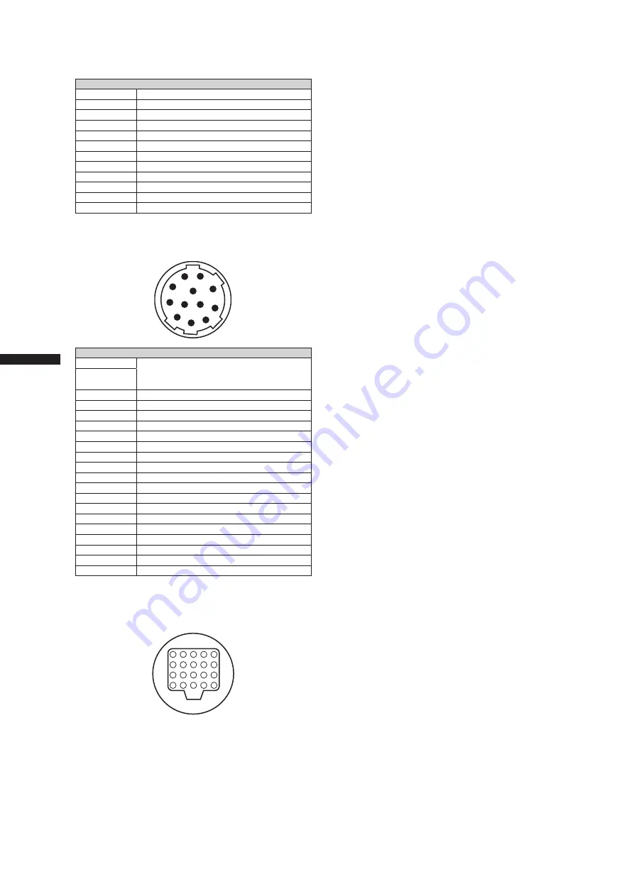
Connector signal description

C

h

ap

te

r 1
0 S
p

ec

ifi

ca

tio

n

s

LENS

1

RET-SW

2

REC-START/STOP

3

GND (ground)

4

IRIS-AUTO

5

IRIS-CONT

6

UNREG +12V (max. 0.4 A)

7

IRIS-POSI

8

IRIS-G-MAX

9

EXT-POSI

10

ZOOM-POSI

11

FOCUS-POSI

12

SPARE

Manufacturer Part No.   HR10A-10R-12SC(71) 

(Hirose Electric Co.)

1

2

4

5

6

7

8

9

10

11

12

3

VF

1

NOREG +12V
11 to 17 V approx. 0.2 A for the supplied 
viewfinder (max. 0.3 A)

2

3

NC

4

B-Y GND

5

R-Y GND

6

VF VIDEO

7

VIDEO GND

8

VF CLK

9

VF WR

10

VF DATA

11

UNREG GND

12

ZEBRA SW

13

NC

14

NC

15

NC

16

NC

17

NC

18

NC

19

NC

20

Chassis ground

Panasonic Part No.  K1AB102H0001
Manufacturer Part No.   HR12-14RA-20SC 

(Hirose Electric Co.)

20

19

18

17

16

15

14

13

12

11

10

9

8

7

6

5

4

3

2

1

Summary of Contents for AG-HPX500

Page 1: ...fully and save this manual for future use S0407T1067 P D Printed in Japan VQT1G18 1 ENGLISH Operating Instructions Memory Card Camera Recorder FRANÇAIS Pour des explications en français veuillez vous reporter au CD ROM fourni Model No AG HPX500P Model No AG HPX500E ...

Page 2: ...area is likely to cause harmful interference in which case the user will be required to correct the interference at his own expense Warning To assure continued FCC emission limit compliance the user must use only shielded interface cables when connecting to external units Also any unauthorized changes or modifications to this equipment could void the user s authority to operate it Caution The inter...

Page 3: ...s small chemical waste NETHERLANDS Voor de primaire voeding en het reservegeheugen van het apparaat wordt gebruikgemaakt van een batterij Wanneer de batterij is uitgeput mag u deze niet gewoon weggooien maar dient u deze als klein chemisch afval weg te doen TO REMOVE BATTERY Main Power Battery Ni Cd Ni MH Li ion Battery To detach the battery please proceed in the reverse order of the installation ...

Page 4: ...eral Public License GPL and GNU Lesser General Public License LGPL and users are hereby informed that they have the right to obtain change and redistribute the source codes of this software Details on GPL and LGPL can be found on the installation CD provided with the unit Refer to the folder called LDOC Details are given in the original English language text To obtain the source codes go to the fo...

Page 5: ...g Modes 40 Pre recording PRE REC 40 Interval recording INTERVAL REC 40 One shot recording ONE SHOT REC 41 Loop recording LOOP REC 42 Hot Swap Recording 42 Recording Check Function 43 Shot Marker SHOT MARK Recording Function 43 Text Memo Recording Function 43 Normal and Variable Speed Playback 44 Video and recording formats 45 Multiple HD SD formats 45 Selecting recording signals in CAMERA MODE 45 ...

Page 6: ...D memory cards 82 Memory Card Usage 83 Power Supply 84 Mounting the Battery and Setting the Battery Type 84 Use of the external DC power supply 86 Mounting the Viewfinder and Adjusting its Position 88 Mounting the Viewfinder 88 Adjusting Viewfinder Right Left Position 88 Diopter Adjustments 89 Screen Adjustments 89 Removing the Viewfinder 90 Mounting and Adjusting the Lens 91 Mounting the Lens 91 Adju...

Page 7: ...D FUNCTION SD memory card setting screen 128 LENS SETUP screen 128 OTHER FUNCTIONS screen 129 OPTION MENU screen 130 Connecting to External Devices Using USB2 0 Port PC mode 131 Procedures for establishing a connection with a PC 131 Connecting to External Devices Using the IEEE1394 Connector PC mode 132 Procedures for establishing a connection with a PC 132 Procedures for connecting a hard disk 13...

Page 8: ...The camera supports recording in 20 HD and SD image formats making it ready for news gathering program production film making and other applications anywhere in the world 1080i 720P HD recording uses the DVCPRO HD codec for broadcast use while SD recording is performed in DVCPRO50 DVCPRO DV multi codec Variable frame rate makes speed effects possible when 720P format is selected This camera comes w...

Page 9: ...red You can also save up to 4 files to an SD memory card and load the files from the card Shooting assist functions User buttons Three user buttons each of which can be assigned a frequently used function for immediate access Focus assist Displays a frequency distribution graph of the video signal as an aid in focusing Eight files for correcting lens aberration and four files for correcting shading fo...

Page 10: ...der Card selection A card in any slot can be instantly selected switched to in standby mode 2 Recorded content can be quickly passed on to editing or transferred to minimize interruptions in recording making it far more efficient than systems where tapes or disks have to be exchanged Hot swap recording Cards can be replaced during recording A full memory card can be replaced while recording is made...

Page 11: ...e filled with text on a PC P2 Viewer SD memory card slot The camera provides an SD memory card slot for saving and loading scene files and user settings A metadata upload file created using P2 Viewer containing the name of the person who shot the video the name of the reporter the shooting location or a text memo and other information can be saved to an SD memory card This data file can be loaded as c...

Page 12: ...ing and smooth editing and dubbing Flow of shooting playing and saving The setting values such as the user file are saved to and read from the SD memory card P2 card You can use the following features HD High Definition recording Multi format recording Variable frame rates Slow quick motion recording Maximum 4 channel uncompressed digital audio recording P2 mode shooting and playback Pages 30 and ...

Page 13: ...E1394 SBP 2 IEEE1394 Windows Macintosh Serial Bus Protocol 2 The data file is transferred for nonlinear editing on your computer or other unit The unit directly controls the external hard disk drive and transfers the data file to it The contents can be transferred as a data stream digital dubbing Connecting external devices via the USB connector Page 131 Connecting external devices via the IEEE139...

Page 14: ... type Battery plate Battery NP 1 type NP L7 battery Charger ENDURA E 7 7S ENDURA E 10 10S SD Memory cards P2 Cards External power supply AG MC200G AJ MC700P Microphone Phantom 48 V Viewfinder AJ VF15B AJ VF20WB AG VF11G SHAN TM700 Tripod adapter AJ HT901G Hard carrying case Rain cover SHAN RC700 AJ SC900 Soft carrying case AG HPX500P E For the latest information on P2 cards and SD memory cards not...

Page 15: ...ing the Shoulder Strap page 101 7 Lens mount 2 3 inch bayonet type The lens is attached here For details refer to Mounting the Lens page 91 8 Lens lever Tighten this lever to lock the lens to the lens mount For details refer to Mounting the Lens page 91 9 Lens mount cap To remove the cap raise the lens lever When the lens is not mounted replace the cap 10 Lens cable microphone cable clamp This cla...

Page 16: ...4 AUDIO LEVEL CH3 CH 4 audio channel 3 4 recording level adjustment controls Set the menu option AUTO LEVEL CH3 AUTO LEVEL CH4 to OFF in the AUDIO SETUP screen to use these controls to adjust the recording level of audio channels 3 and 4 5 AUDIO IN audio input selector switch Use this switch to select the signals recorded through Audio Channels 1 4 FRONT Signal from the microphone connected to the...

Page 17: ...al from a passive microphone is input The unit supplies power to the remote microphone Note Power is supplied when R MIC POWER in the AUDIO SETUP screen is set to ON 8 FRONT AUDIO LEVEL audio recording level adjustment control This control adjusts the recording level of Audio Channels 1 and 2 Level adjustment is possible when the AUDIO SELECT switch is set to MAN Use the menu options FRONT VR CH1 ...

Page 18: ... and 4 CH2 4 Audio Channel 2 Audio Channel 4 3 MONITOR ALARM volume control Used to control the volume of sound output from the monitor speakers and earphones It also adjusts the alarm sound volume 4 Speakers The speakers output EE sound during recording and reproduced sound during playback The speakers emit an alarm sound when the warning lamp blinks and or the indicator activates EE sound and pl...

Page 19: ... shutter speed For more information see Setting the Electronic Shutter page 53 4 AUTO W B white black BAL switch AWB Automatically adjusts the white balance Set the WHITE BAL switch on the side to A or B and use this switch to adjust the white balance which takes a few seconds The adjusted value is stored in memory When the WHITE BAL switch is set to PRST and the color temperature is indicated wit...

Page 20: ...gh a window The subject is a high contrast scene 7 WHITE BAL white balance memory selector switch Used to select the white balance adjustment method PRST Use this when you have no time to adjust the white balance The value for the white balance is factory set to 3200 K While the setting menu or the color temperature is displayed turn the AUTO W B BAL switch to AWB to set the color temperature to 3...

Page 21: ...21 Chapter 2 Parts and their Functions 31 29 23 28 30 27 16 15 13 17 14 18 12 32 33 25 24 22 20 19 21 10 11 10 34 26 ...

Page 22: ... While depressing this button slide the door to the left 21 USB 2 0 connector Connect a USB 2 0 cable to this connector Select USB DEVICE under the menu option PC MODE in the OTHER FUNCTIONS screen to send data via the USB 2 0 connector The camera cannot be used for recording playback or clip operations when this function is used For details refer to Connecting to External Devices Using USB2 0 Por...

Page 23: ... to Connecting to External Devices Using the IEEE1394 Connector PC mode page 132 30 SDI OUT connector This connector outputs SDI signals Use the menu option CMPNT SDI SEL in the setting menu OUTPUT SEL screen to select AUTO 1080i 480i or 576i This connector does not support up conversion 31 SCENE FILE dial This dial allows you to load and set the shooting conditions for a scene file already recorde...

Page 24: ...umbnails and access menu functions For details see Manipulating Clips with Thumbnails page 103 4 MODE button This button toggles between the CAMERA mode and MCR mode For details see Shooting and Recording Playback Function Section page 19 5 CURSOR and SET buttons Use these buttons to manipulate menus the menu bar and thumbnails The four triangular buttons are CURSOR buttons and the square center b...

Page 25: ...n are open press this button to reset all set values to 0 and press the SET button to preset 6 COUNTER counter display selector button The LCD monitor and the viewfinder show the counter value time code user bit and frame rate data 7 TCG time code selector switch This switch is used to specify the stepping mode for the built in time code generator F RUN Select this position to continuously advance ...

Page 26: ...TALLY switch is set on ON the rear tally lamp behaves in the same way as the back tally lamp 5 Mode LED Shows the camera unit mode CAM Lights red in CAMERA mode MCR Lights green in MCR mode PC Lights orange in PC mode 1 LCD monitor The LCD monitor displays the video in the viewfinder Alternatively it can show clips on the P2 card in a thumbnail format In thumbnail display mode you can use the thumb...

Page 27: ...nd output camera signals are not affected 5 CONTRAST control Used to adjust the contrast of the video image in the viewfinder Recorded video and output camera signals are not affected 6 BRIGHT control Used to adjust the brightness of the video image in the viewfinder Recorded video and output camera signals are not affected 7 Front tally lamp This lamp goes on during recording when the TALLY switch ...

Page 28: ...rence Area 00 00 Greenwich 00 30 01 00 Azores Islands 01 30 02 00 Mid Atlantic 02 30 03 00 Buenos Aires 03 30 Newfoundland Island 04 00 Halifax 04 30 05 00 New York 05 30 06 00 Chicago 06 30 07 00 Denver 07 30 08 00 Los Angeles 08 30 09 00 Alaska 09 30 Marquesas Islands 10 00 Hawaii 10 30 11 00 Midway Island 11 30 12 00 Kwajalein 11 30 Norfolk Island 13 00 10 30 Lord Howe Island 12 00 New Zealand ...

Page 29: ...n the JOG dial button to set YEAR to 2007 then press the JOG dial button A year between 2000 to 2030 can be set 9 Turn the JOG dial button to select MONTH then press the JOG dial button 10 Turn the JOG dial button to set MONTH to DEC then press the JOG dial button 11 Set DAY HOUR and MIN in the same way as setting YEAR and MONTH This is a 24 hour clock PUSH MENU TO RETURN 2007 MONTH DEC DAY 25 HOU...

Page 30: ...he slide out door to the left The door opens 3 Insert a P2 card in a P2 card slot Press in the card until the eject button pops up 4 Tilt up the popped up EJECT button Insert a P2 card into the AG HPX500P E The P2 CARD ACCESS LED for the appropriate slot indicates the status of the P2 card For how the P2 card status is indicated see P2 CARD ACCESS LED and status of P2 cards page 32 P2 Cards The ca...

Page 31: ... Restoring Clips page 108 If a P2 card being formatted is removed it may be not be formatted properly In this case the viewfinder displays TURN POWER OFF If this message appears turn off the power then restart the AG HPX500P E to reformat the card If a P2 card is inserted while another P2 card is being played back the inserted P2 card is not recognised and the P2 CARD ACCESS LED for that card does ...

Page 32: ...ording P2 card recording times Model number AJ P2 C004HG AJ P2 C008HG AJ P2 C016RG Capacity 4GB 8GB 16GB DVCPRO HD Approx 4 min Approx 8 min Approx 16 min DVCPRO HD 720P 24PN Approx 10 min Approx 20 min Approx 40 min DVCPRO HD 720P 30PN 720P 25PN Approx 8 min Approx 16 min Approx 32 min DVCPRO50 Audio 4CH Approx 8 min Approx 16 min Approx 32 min DVCPRO DV Audio 2CH Approx 16 min Approx 32 min Appr...

Page 33: ...event data loss in transferring P2 card data to a PC or write back PC data on a P2 card use P2 Viewer which can be downloaded from the Web site listed below Supported operating systems Windows 2000 Windows XP Windows Vista https eww pavc panasonic co jp pro av Follow the steps below to use general software such as Microsoft Windows Explorer or Apple Finder to transfer the data to a PC Be sure to u...

Page 34: ...y with a fully charged battery check battery installation 3 Insert a P2 card and ensure that the P2 CARD ACCESS LED stays on in orange or green Then close the slide out door When more than one P2 card slot contains a P2 card the card in the slot with the lowest number is used first However regardless of slot number a P2 card inserted later will not be accessed until the other cards have been used E...

Page 35: ...ote The slot selected for recording cannot be changed when recording has started Use the USER MAIN USER1 USER2 item in setting menu SW MODE screen to assign functions to the USER MAIN USER1 USER2 button Shooting White Black Balance Adjustment to Recording Completion For shooting follow the steps below 1 Use the ND FILTER control to select a filter according to light conditions 2 When the white bala...

Page 36: ...tion Buttons In CAMERA mode all operation buttons REW FF PLAY STILL STOP are disabled Normal Recording Pressing the REC START STOP button starts recording of video and sound on the P2 card The video and audio including additional information recorded in one session is referred to as a clip Note Pressing the REC START STOP button will not immediately stop data write operations to a P2 card in the f...

Page 37: ...annot change the frame rates while recording You can select any of 11 recording frame rates ranging from 12 frames per second fps to 60 fps See Video and Recording Formats page 45 There may be slight discrepancies between the recording frame rate displayed and the frame rate at which the images are actually recorded Refer to the table below 59 94 Hz 50 Hz Recording frame rate displayed Frame rate ...

Page 38: ... other settings 720P 60P or 720P 50P The default setting is 30FRAME at a recording frame rate of 30P and 24FRAME 25FRAME at 25P at a recording frame rate of 24P 4 Press the REC START STOP button Pressing the REC START STOP button starts standard recording in the VFR mode the sound is also recorded Note In the case of a nonlinear editing system that supports Varicams equipped with an effective fram...

Page 39: ...ve Mode Selecting 30P 24P or 24PA 1080i or 480i mode in the REC FORMAT in the setting menu RECORDING SETUP screen enables shooting in the progressive mode 30P mode This mode enables shooting 30 fps video in the progressive mode The 30 fps video signal is converted to a 60 field interlaced signal for output and recording This guarantees high quality video output Ao Ae Bo Be Co Ce Do De Eo Ee Fo Fe G...

Page 40: ...CORDING SETUP screen 3 Press the REC START STOP button This setting will record audio and video a time period prior to start of recording The following recording modes will disable the pre recording function and start respective recording function when selected Recording of video input via the IEEE1394 connector When changing recording formats After a change from playback to recording During inter...

Page 41: ...he OPERATION TYPE item in the menu option SCENE FILE screen and REC FORMAT item in the menu option RECORDING SETUP screen are set as described below For details on menu operation refer to Using the menus page 116 OPERATION TYPE item VIDEO CAM Recording format They are available at 1080i 60i 50i 1080i 30P 25P 720P 60P 50P 720P 30P 25P or in SD at 60i 50i 30P 25P 2 Select ONE SHOT in the REC FUNCTIO...

Page 42: ...ions appear to the left of the operation status display During recording L REC stays lit During a pause L PAUSE stays lit When remaining memory is low P2 LACK L blinks Note Use a P2 card with at least one minute of remaining recording time Switching to the mode check screen displays the minimum guaranteed recording time This function is not available during IEEE1394 input The pre recording functio...

Page 43: ...rded clip Pressing this key a second time displays MARK OFF and the shot mark is deleted Note Shot marks can be added also in the thumbnail display The shot marker function is not available during loop recording When this function is not available pressing this button displays INVALID Shot marks cannot be set or deleted during playback Shot marks for video data created in a single hot swap recordi...

Page 44: ...clip information If this is the case the thumbnail screen displays UPDATING If a P2 card is inserted while another P2 card is being played back the clips on the inserted P2 card will not be played back A P2 card inserted during playback will be recognised after playback ends If you perform variable speed playback on a clip split across more than one P2 card sound may disappear for a moment This is...

Page 45: ...mes 3 The listed recording times are for four 16 GB P2 cards Using only one 16 GB card will reduce the recording time to 1 4 In addition to the video format and codec function setup and the number of cuts will affect the recording time Selecting recording signals in CAMERA MODE CAMERA MODE allows you to record video shot with the camera Use the setting menus listed below to select recording signal...

Page 46: ...ETUP screen In SD mode 480i 576i you can select DVCPRO50 or DVCPRO DV for recording 1394 connector signals or as playback mode to play back P2 card clips In a change from CAMERA mode to MCR mode the 480i 576i REC MODE is retained Selecting video output CAMERA MODE and MCR mode allow you to select video output format Use the setting menus listed below to select video output Setting menu Setting CMP...

Page 47: ...HD 720P 29 97P 4ch 5 AUTO 720P 59 94P 1 4ch 5 720P 59 94P 1 525i 59 94i No output 720P 24PN 24P native recording at 24P capture 3 DVCPRO HD 720P 23 98P 1080i 1080i 59 94i 1080i 59 94i 480i 525i 59 94i 525i 59 94i 480i 60i 60i DVCPRO50 DVCPRO DV 4 480i 59 94i 4CH or 2CH 6 Disabled 525i 59 94i 4CH or 2CH 6 525i 59 94i 525i 59 94i DVCPRO50 DVCPRO DV 4 525i 59 94i 480i 30P 30P over 60i 480i 24P 24P ov...

Page 48: ...0i 50i 1080i 50i 576i 625i 50i 625i 50i 720P 25PN 25P native recording at 25P capture 8 DVCPRO HD 720P 25P 4ch 9 AUTO 720P 50P 7 4ch 9 720P 50P 7 625i 50i No output 1080i 1080i 50i 1080i 50i 576i 625i 50i 625i 50i 576i 50i 60i DVCPRO50 DVCPRO DV 4 625i 50i 4CH or 2CH 6 Disabled 625i 50i 4CH or 2CH 6 625i 50i 625i 50i DVCPRO50 DVCPRO DV 4 625i 50i 576i 25P 25P over 50i 4 Select DVCPRO50 or DVCPRO D...

Page 49: ...H 7 Disabled 525i 59 94i 4CH or 2CH 7 525i 59 94i 525i 59 94i DVCPRO50 DVCPRO DV 6 525i 59 94i SYSTEM FREQ setting menu 50 Hz Format setting Recording status Output setting Output status MCR FORMAT 1394 recording and playback format Recording and playback audio channel CMPNT SDI SEL SDI OUT SDI OUT AUDIO COMPONENT OUT VIDEO OUT Playback of 1394 output 1080i 50i DVCPRO HD 1080i 50i 4ch AUTO 1080i 5...

Page 50: ...adjust the iris to obtain a 70 indication 5 Turn the AUTO W B BAL switch toward AWB and release it The switch returns to the central position with the white balance automatically adjusted 6 During an adjustment the viewfinder displays the following message AWB Ach ACTIVE To record high quality video with the AG HPX500P E the black and white balances must be adjusted according to conditions For high...

Page 51: ...K When the white balance has not been automatically adjusted When the white balance has not been successfully adjusted the viewfinder displays an error message Error message Description AWB NG The color temperature is too high or too low LOW LIGHT There is insufficient light LEVEL OVER There is too much light Viewfinder displays related to white balance See Viewfinder Screen Status Displays page 67 Ad...

Page 52: ... and the following message will appear ABB END The adjusted value is automatically stored in the memory Note Ensure that the lens connector is connected and the lens iris is CLOSE During a black balance adjustment light is automatically cut off Retaining black balances Each value in memory is retained even if the video camera recorder is turned off ...

Page 53: ...000 S S 1 60 1 15 1 30 1 100 1 120 1 250 S S 1 500 1 1000 1 2000 1 50 1 120 1 250 1 500 1 1000 S S 1 60 60 Hz mode For 60i and 60P recording For 30P recording For 24P recording excluding 720P 24P and 720P 24PN For 24P recording at 720P 24P or 720P 24PN 1 500 1 1000 1 15 1 50 1 120 1 250 S S 1 60 50 Hz mode Note In any electronic shutter mode a slower shutter speed will reduce camera sensitivity In...

Page 54: ...ed can be switched seamlessly between 1 60 0 and 1 249 8 seconds using the JOG dial button Speed switchover is enabled in 60i mode Range of variation in each mode 59 94 Hz mode 60P 60i mode 1 60 0 to 1 249 8 30P 30PN mode 1 30 0 to 1 249 8 24P 24PA 24PN mode 1 24 0 to 1 249 8 FILM CAM mode 10 0d to 360 0d 50 Hz mode 50P 50i mode 1 50 0 to 1 248 9 25P 25PN mode 1 25 0 to 1 248 9 FILM CAM mode 10 0d...

Page 55: ...gns recording check SPOTLIGHT Assigns auto iris control on off for spotlight BACKLIGHT Assigns auto iris control for backlight compensation BLACKFADE Assigns blackfade WHITEFADE Assigns whitefade GAIN 18dB Assigns a gain increase of 18 dB TEXT MEMO Assigns text memo recording SLOT SEL Assigns P2 card slot selection SHOT MARK Assigns shot marker function LVL METER Assigns channel level indicator fu...

Page 56: ...O SETUP Adjusting Recording Levels To adjust the recording levels for Audio Channels 1 and 2 follow the steps below 1 Position the MONITOR SELECT CH1 2 CH3 4 selector switch at CH1 2 so that the audio level meter on the display window will provide CH1 and CH2 indications Ensure that the channel indications displayed in the window are 1 and 2 2 Position the AUDIO SELECT CH1 CH2 switch at MAN This A...

Page 57: ...ewfinder screen and use the FRONT AUDIO LEVEL control to adjust the appropriate audio channel so that no excessive audio signals will be admitted Selecting Function for the FRONT AUDIO LEVEL Control Use the menu options FRONT VR CH1 and FRONT VR CH2 to determine whether or not to enable control of selected input signals using the FRONT AUDIO LEVEL control Selecting the ON setting enables FRONT AUDI...

Page 58: ...by a REC WARNING or other abnormality User bits There are two types of user bits The user bits UB that are recorded in the subcode area and the user bits VITC UB that are recorded in the VIDEO AUX area The subcode user bits enable the recording of user settings time date time code and similar values the frame rate data for camera capture external input values via TC IN or 1394 connector input VITC...

Page 59: ...me code input via 1394 regardless of setting 30 30 30 24 switchable 7 Depends on user bits mode 5 Records VIDEO AUX area user bits input via 1394 regardless of setting 720P 30PN Not related Not recorded Playback 30 frame Not recorded Playback 30 frame Playback 30 Playback locked at 30 Not recorded Not recorded playback frame rate data is converted and generated in synch with video pull down 720P 2...

Page 60: ...o slave lock to user bit input to the TC IN connector set the setting menu TC IN UB REGEN on the RECORDING SETUP screen to ON To slave lock to user bit input to the 1394 connector during recording of input from the 1394 connector in MCR MODE set the setting menu 1394 UB REGEN to ON In slave mode the UB indicator is highlighted In this status the UB MODE setting is disabled A slave relationship onc...

Page 61: ...g menu UB MODE to FRM RATE records the information also to the user bits in the subcode area In playback of clips recorded at 720P native the same frame rate information as that obtained in playing back the user bits in the VIDEO AUX area is also output to the user bits in the subcode area Frame rate information Frame rate video pull down and time code user bits are related as described below Came...

Page 62: ...29 00 h 00 m 00 s 00 TC PRESET SEL PUSH PUSH REC RUN PRESET PUSH button Shifts the target highlighted digit to the right button Shifts the target highlighted digit to the left button Increases the highlighted number by one button Decreases the highlighted number by one SET button Use to confirm set time code value Pressing the RESET button will reset any time code setting to 0 5 Press the SET butto...

Page 63: ... 30P capture at 30PN and other than 25P capture at 25PN 24PN recording at 60P capture Video output 0 1 2 3 22 23 24 25 58 59 60 61 62 63 67 68 Rec start Rec stop Skips Rec start Output time code 00 00 00 00 00 00 00 01 00 11 00 12 00 29 01 00 01 01 02 20 02 20 Recorded video 0 1 2 3 22 23 24 25 58 59 60 61 62 63 67 68 Recorded time code 00 00 00 01 00 02 00 03 00 22 00 23 01 00 01 01 02 10 02 11 0...

Page 64: ... 1 Turn on the POWER switch 2 Position the TCG switch at F RUN 3 Set the COUNTER button to TC 4 Supply a phase relationship reference time code that conforms to the time code requirements and reference video signals to the TC IN and GENLOCK IN connectors respectively Now the built in time code generator is locked with the reference time code When locked to an external time code generator the time ...

Page 65: ... interlaced and progressive scanning there may be breaks in the video and time code Note that switching to MCR mode will disrupt GENLOCK synchronization resulting in loss of image stability When the 24P or 24PA is selected and the time code is externally locked be sure to input a non drop frame time code The time code cannot be externally locked when drop frame mode is selected When the time code ...

Page 66: ...OUT COMPOSITE Disabled Connection diagram 1 VTR etc TC OUT REF SDI or VIDEO OUT AG HPX500P E TC HD signal or SD signal TC IN GENLOCK Connection diagram 2 Down conversion SD device REF TC COMPOSITE SDI AG HPX500P E TC SD signal Delay TC IN GENLOCK Counter Setting and Display Pressing the COUNTER button to view the counter displays the counter value on the time code indicator in the LCD and in the v...

Page 67: ...een page 126 Viewfinder Screen Status Displays 3 BATT battery Lamp This lamp starts blinking a few minutes before the battery charge starts to run out and stays illuminated after the battery is completely flat The battery should be replaced before it is nearly flat so that operation will not be interrupted For more information see Warning System page 142 4 SAVE Lamp This lamp lights when the SAVE swi...

Page 68: ...60P progressive mode 60 frames sec FR 30P 30P progressive mode 30 frames sec FR 24P 24P progressive mode 24 frames sec FR24PA 24P advanced mode 24 frames sec FR50I 50i interlace mode 50 fields sec FR50P 50P progressive mode 50 frames sec FR25P 25P progressive mode 25 frames sec In FR24P and FR24PA modes the last digit indicates the frame conversion sequence information Note When TC tc and UB are lo...

Page 69: ... too low C TEMP Adjusting the auto white balance turning the WHITE BAL switch or turning on the power displays the color temperature when COLOR TEMP in the setting menu SCENE FILE screen is set to something other than 0 8 Marker luminance display When markers are displayed the brightness level around the center of the screen is indicated as 0 to 99 99 appears if the percentage is over 99 9 Calenda...

Page 70: ...icates the switch position currently selected Also indicates white balance operation when AWB is set to preset 22 Center marker display Markers are displayed when the MARKER item in the setting menu DISPLAY SETUP screen is set to ON 23 Scene file name display Indicates name of SCENE FILE F1 to F6 24 Media remaining memory display Setting the setting menu P2 CARD REMAIN DISPLAY SETUP to ONE CARD dis...

Page 71: ...E CARD The card cannot be used since it does not comply with the specified standard DIR ENTRY NG CARD Indicates a card where folder location has become corrupted This type of card cannot be used for special recording modes interval ONE SHOT and loop recording A warning appears when such a P2 card is inserted in a P2 device or when recording is completed RUN DOWN CARD Indicates that a P2 card has ne...

Page 72: ...ried out again replace the card with another one ERROR Other type of trouble 1394 This is displayed when trouble has occurred in the 1394 connections or signals 1394 INITIAL ERROR Connection error 1394 INPUT ERROR Input error 1394 INPUT ERROR OTHER FORMAT Wrong input format LOW BATTERY Indicates that the battery is exhausted Camera status display AWB AWB indicator ABB ABB indicator AWB P3 2 K AWB ...

Page 73: ...at and system frequency indication 5 Information display 6 Squeeze information 8 Marker luminance display 9 Calendar 10 Recording playback frame rate display 1 11 Shutter speed 12 Audio level meter display 13 IRIS display 14 Zoom position display 15 Auto iris control display 16 Remaining battery charge 4 18 Recommended ND filter 19 ND filter display 20 Gain display 2 21 WHITE BAL switch position ind...

Page 74: ... from the setting menu DISPLAY SETUP screen For directions on navigating the menu see Using the menus page 116 PUSH MENU TO RETURN MARKER SAFETY ZONE DATE TIME LEVEL MATER ZOOM CARD BATT P2CARD REMAIN ZEBRA DETECT DISPLAY SETUP OFF ON ON ON ON 80 90 TOTAL You can also press the USER button to which the MARKER function has been assigned to turn the marker on and off ...

Page 75: ...ent camera recorder failure do not allow undue force to be applied to the monitor when it is open 4 Use the menu option LCD SET DISPLAY SETUP to adjust the brightness color level and contrast of the screen For details on menu operation refer to Using the menus page 116 At LCD SET of the DISPLAY SETUP screen select YES PUSH MENU TO RETURN LCD BACKLIGHT NORMAL LCD SET SELF SHOOT S CROP DOWNCON MODE ...

Page 76: ...is very cold the video image in the LCD monitor will appear slightly darker immediately after the power is turned on Once the interior of the camera recorder warms up the LCD monitor delivers normal brightness When the SAVE switch is set to ON the LCD monitor is forcibly disabled Self portrait Shooting When shooting with the LCD display angled 180 degrees towards the lens you can set the menu opti...

Page 77: ...F6 Default value F1 Current value SCENE FILE Current operating status values F2 Current value F3 Current value F4 Current value F5 Current value F6 Current value F1 Saved value SCENE FILE Saved camera values F1 F2 F3 F4 F5 F6 SCENE FILE 1 F1 F2 F3 F4 F5 F6 SCENE FILE 2 F1 F2 F3 F4 F5 F6 SCENE FILE 3 F1 F2 F3 F4 F5 F6 SCENE FILE 4 USER FILE1 USER FILE2 USER FILE3 USER FILE4 USER FILE initial value ...

Page 78: ...m the insertion slot Take hold of the SD memory card and remove it Close the lid SD memory cards must not be used or stored in an environment where they may be Exposed to high temperatures humidities Exposed to water droplets or Electrically charged For storage the SD memory card must be kept inserted into the AG HPX500P E with the lid closed Formatting Writing and Reading an SD memory card Open t...

Page 79: ...ing you can retrieve the necessary file instantly using scene file dial You can also use menu options to change set scene file values A modified scene file can be saved to each scene file dial position During recording the OPERATION TYPE and FRAME RATE settings remain unchanged even when the scene file is changed To change these settings set the camera recorder to recording standby state Factory setting ...

Page 80: ... the cursor to YES Then press the JOG dial button SKIN TONE DTL V DETAIL FREQ NAME EDIT MATRIX PUSH MENU TO RETURN SCENE F1 OFF NORM1 THIN YES 5 When the screen shown below appears use the JOG dial button to enter a 6 character file name Turning the JOG dial button changes the character display in the following order space alphabet A to Z numerics 0 to 9 symbols _ If the RESET button is pressed whe...

Page 81: ... CHROMA LEVEL 1 60 3 PUSH MENU TO RETURN SCENE F1 0 0 0 0 SAVE SAVE INITIAL LOAD 3 Turn the JOG dial button to move the cursor to YES Then press the dial button To return to the menu level above press the MENU button YES NO SAVE PUSH MENU TO RETURN SCENE FILE PUSH DIAL PROCESSING appears and the following message is shown when all settings have been completed SAVE COMPLETED After changing the scen...

Page 82: ...16 PUSH MENU TO RETURN USER FILE SD CARD FORMAT SCENE FILE CARD FUNCTIONS YES 3 Select the file number 1 to 4 using the JOG dial button Press the JOG dial button again to confirm the setting READ WRITE FILE 1 NO FILE FILE 2 NO FILE TITLE RELOAD FILE SELECT PUSH MENU TO RETURN SCENE FILE SD CARD 1 FILE 3 NO FILE FILE 4 NO FILE 4 Select WRITE using the JOG dial button and press the JOG dial button REA...

Page 83: ...SD memory card If WRITE NG WRITE PROTECT appears release the protected status of the SD memory card If WRITE NG CANNOT ACCESS appears quit all other operations such as playback before proceeding If WRITE NG ERROR appears the SD memory card may be defective Replace it Memory Card Usage Use only cards that conform to the SD card standard or the SDHC standard in this camera Be sure to use a mini SD c...

Page 84: ...the battery pack with the battery charger before using it Please refer to the battery charger s instruction manual for information about charging Mounting the Battery and Setting the Battery Type Using an Anton Bauer Battery Pack 1 Mount an Anton Bauer battery pack Note The Anton Bauer battery holder includes both a power supply output connector for lighting and a lighting control switch which are...

Page 85: ...wing Anton Bauer batteries can be used PROPAC14 TRIMPAC14 HYTRON50 HYTRON140 DIONIC90 DIONIC160 Using an NP 1 type battery pack When replacing the battery holder consult your distributor 1 Remove the battery holder 2 Mount the NP 1 type battery case on the camera recorder Tighten the mounting screws Tighten the power contact screws Insert the upper part of the removed cover in the direction of the...

Page 86: ...n Note For information about the V mount adapter plate please contact the store where you purchased the camera recorder Use of the external DC power supply 1 Connect the external DC power supply to the DC IN socket on the unit Attach the two ferrite cores provided to both ends of the DC cable in such a way that the ferrite cores fit within about 5 cm 2 inches from the connectors as shown below Clos...

Page 87: ...IN Socket Pin No Signal 1 12V GND 4 2 3 Notes When both the battery pack and the external DC power supply are connected power is supplied from the external DC power supply The battery can be removed or mounted while using an external DC power supply When using an external DC power supply make sure you turn on the external DC power supply before turning on the camera recorder s power switch If this...

Page 88: ...or 3 Loosen the viewfinder right left positioning ring 4 Turn the viewfinder securing screw counterclockwise to cancel the safety mechanism and slide the viewfinder in the direction of the arrow 5 Turn the viewfinder securing screw clockwise to prevent it from falling off 6 Tighten the viewfinder right left positioning rings Note Be sure to firmly tighten the viewfinder securing screw on the viewfinder ri...

Page 89: ...owing controls to adjust viewfinder screen Brightness Turn the BRIGHT control Contrast Turn the CONTRAST control Peaking Turn the PEAKING control 1 Turn on the POWER switch on the camera 2 Set the OUTPUT switch of the camera to BARS 3 Turn the viewfinder BRIGHT and CONTRAST controls to adjust viewfinder brightness and contrast Turn the PEAKING control to obtain a sharp image A sharper viewfinder image...

Page 90: ...he POWER switch is turned off 2 Loosen the viewfinder right left positioning rings 3 Turn the viewfinder securing screw counterclockwise slide the viewfinder in the direction of the arrow and remove it 4 Disconnect the viewfinder cable and microphone cable from the clamp and remove them Loosen Viewfinder securing screw ...

Page 91: ...p center of the lens mount with the center mark of the lens 3 Lower the lens clamping lever to clamp the lens 4 Secure the cable through the cable clamp and plug it into the LENS connector 5 Adjust the lens flange back Notes Please refer to the lens instruction manual for guidance on lens handling When the lens is removed install the mount cap to protect the device LENS Connector Mark Mount Cap Len...

Page 92: ...e zoom ring to the telephoto position either manually or by electric drive 6 Aim the lens at the flange back adjustment chart and turn the distance ring to bring the chart into focus 7 Set the zoom ring to the wide angle position and turn the F f ring to bring the chart into focus While focusing take care not to move the distance ring 8 Repeat Steps 5 to 7 until the lens is in focus at both the tel...

Page 93: ...loring may occur in the vertical direction near the open setting of the lens iris even when the white shading has been adjusted This is an optical characteristic and not indicative of a failure 1 Place the camera in the adjustment mode 1 Mount a lens on the camera Do not forget to connect the lens cable 2 Turn off the electronic shutter and set the gain to L 0 dB 3 If the lens comes with an extend...

Page 94: ...e between F4 and F11 Make sure the electronic shutter is set to off 3 Adjust white and black balance 1 Set the WHITE BAL switch to A or B and use the AUTO W B BAL switch to make an automatic white balance adjustment 2 Use the AUTO W B BAL switch to make an automatic black balance adjustment 3 Again use the AUTO W B BAL switch to make an automatic white balance adjustment 4 Repeat the operation in ...

Page 95: ... our Web site at the address given below for details on new lenses compatible with this function and any changes in this function https eww pavc panasonic co jp pro av Checking CAC Operating Status Press the DISP MODE CHK button when no menu is open CAC is running if CAC appears in the upper right corner of the screen CAC Checking CAC data number and CAC data during operation 1 Open the setting me...

Page 96: ...ready been loaded READ NG CAC FILE FULL appears To load new file delete an existing file before loading the new file For details see Deleting CAC File page 96 READ NG FORMAT ERROR indicates the file cannot be used and will not be loaded Make sure the file is in a format the camera supports and that the file on the SD card is not corrupted Deleting CAC File 1 Open the setting menu LENS SETUP screen For d...

Page 97: ...confirmation screen PUSH MENU TO RETURN SHADING USER SHADING SELECT LENS SETUP DEFAULT CAC PROPERTY CAC CARD READ CAC FILE DELETE CAC FILE INIT IRIS ADJUST YES 3 Select YES in the confirmation screen and press the JOG dial button CAC FILE INIT PROCESSING COMPLETED is displayed to indicate that initialization is completed The LENS SET UP screen appears after completion NO YES CAC FILE INITIAL CAC FIL...

Page 98: ... microphone holder 2 Mount the microphone and tighten the clamping screw 3 Connect the microphone cable to the MIC IN jack on the camera 4 Set the AUDIO IN switch to FRONT depending on the audio channel to be recorded Note When the microphone connecting cable is connected to the FRONT2 jack and the AUDIO IN switch CH1 is set to FRONT2 and switch CH2 is set to FRONT sound from the microphone sound ...

Page 99: ... 1 Connect the audio device to the AUDIO IN jack with the XLR cable 2 Set the AUDIO IN switch to REAR for the channel to which the XLR cable is connected 3 Set the LINE MIC 48V selector switch on the rear panel to LINE AUDIO IN Switch AUDIO IN Jack LINE MIC 48V Selector Switch ...

Page 100: ...screw 2 Mount the camera on the tripod adapter Slide the camera forward along the grooves until you hear a click Removing the Camera from the Tripod Adapter While holding the red lever down move the black lever in the direction of the arrow and slide the camera backward to remove it Note If the tripod adapter pin does not return to its original position after the camera has been removed hold the r...

Page 101: ...en the cord Secure with the surface fastener Secure with the surface fastener Attaching the FRONT AUDIO LEVEL Control Knob If you use the FRONT AUDIO LEVEL control frequently attach the accessory knob so that it can be easily operated Remove the screw in the center of the FRONT AUDIO LEVEL control and attach the accessory knob using the screw included When attaching the knob be sure to align the m...

Page 102: ...10G is set to OFF the camera related setting values which have been adjusted or set using the AJ RC10G will be cancelled when the camera power switch is turned OFF Also the setting values cannot be written to an SD memory card However the menu settings performed using the AJ RC10G can be written to an SD memory card Next time the AJ RC10G is connected the setting values will return to the AJ RC10G...

Page 103: ...lete and repair clips Add or delete a shot mark and text memo on the clip thumbnail Format P2 cards and SD memory cards Upload the clip meta data from an SD memory card Thumbnail Operations Thumbnail Overview Thumbnail screens are configured as follows PROPERTY CLIP PROPERTY EXIT CARD STATUS DEVICES PROPERTY SETUP SYSTEM INFO META DATA LOAD EXIT RECORD USER CLIP NAME INITIALIZE PROPERTY OPERATION D...

Page 104: ...sed the menu display is cleared and the original screen is restored 6 Recording mode format display This is where the recording mode and format of the recorded images are displayed 7 Indicators M Shot mark This indicates that a clip has a shot mark W Wide This indicates that a clip has been recorded in the 16 9 aspect ratio wide screen 480i 576i recording Incomplete clip This indicator appears whe...

Page 105: ...MAT CLIPS The clips in the same recording or MCR format are displayed SELECTED CLIPS Display randomly selected clips MARKED CLIPS Display clips with shot marks attached TEXT MEMO CLIPS Clips with text memos are displayed Thumbnails at text memo positions time codes TC total number of memos and the current order of the clips are displayed SLOT CLIPS Display clips recorded in the P2 card inserted in...

Page 106: ...ator The factory setting is ON indication DATA DISPLAY The time display field of the clip offers a choice of Time Code TC User Bits UB Shooting Time TIME or Shooting Date DATE Shooting Time and Date DATE TIME The factory setting is Time Code DATE FORMAT You can specify the display order for the shooting date as either Year Month Day YMD Month Day Year MDY or Day Month Year DMY The factory setting i...

Page 107: ...position to the beginning of the clip Pressing the REW button again moves the pause position to the beginning of the previous clip During a pause pressing the FF button moves the pause position to the beginning of the next clip Holding down the FF button displays the last image in the last clip EOS appears at this time 6 Pressing the STOP button during clip playback stops the playback and returns ...

Page 108: ...tops the deletion operation in the middle Restoring Clips Restores clips that are defective as a result of sudden poweringdown during recording or removal of the P2 card being accessed Note Only those clips with yellow corrupt clip markers can be restored Delete the clips with red corrupt clip markers If the clip cannot be deleted format the P2 card During restoration of the clips however the defe...

Page 109: ...ic co jp pro av See Memory Card Usage page 83 Note The file which was edited by except P2 viewer is displayed as UNKNOWN DATA and may not be read GLOBAL CLIP ID Displays the global clip ID which indicates the shooting status of the clip USER CLIP NAME Displays the clip name specified by the user If the metadata upload file does not contain any data the global clip ID serves as the USER CLIP NAME The ...

Page 110: ...no clip metadata has been read in or if the setting for recording clip metadata has been turned off Same as GLOBAL CLIP ID UMID data TYPE2 USER CLIP NAME to be recorded If clip metadata has been read in Uploaded data COUNT value If no clip metadata has been read in or if the setting for recording clip metadata has been turned off Same as CLIP NAME The COUNT value is indicated as a four digit numbe...

Page 111: ...ing start REC PAUSE recording pause Clip 1 COUNT value 0001 Clip 2 COUNT value 0002 1st card 2nd card If the clip thumbnails are displayed as shown in the example above or their properties are indicated using a P2 device the thumbnail and COUNT value of clip 1 will be displayed Clear the uploaded metadata Select META DATA INITIALIZE and press the SET button Select YES when the confirmation screen i...

Page 112: ...is formatted Formatting SD memory cards SD memory cards can also be formatted from the thumbnail screen With an SD memory card inserted into the camera recorder perform the following operation 1 Press the MODE button to enter the MCR mode The thumbnail screen appears on the LCD monitor 2 Press the thumbnail menu button to open the menu 3 Select OPERATION FORMAT The following screen appears Select ...

Page 113: ...ing 720P 24PN or 720P 30PN recording operation 5 Clip metadata The video and audio formats videographer information and other detailed data are displayed here The audio format is only indicated for 1 to 4CH Use the CURSOR button to select the item and press the SET button For details on the clip metadata see Setting of Clip Meta Data page 109 P2 Card Status Display P2 Card Status Display Settings ...

Page 114: ...splayed 4 Total remaining memory capacity for all cards Displays the total remaining free space for all 4 slots Please note that the remaining capacity of a write protected P2 card is not included in the total remaining capacity When REC FUNCTION RECORDING SETUP is set to LOOP the total remaining memory capacity for all cards indicates the minimum guaranteed recording time for the loop recording W...

Page 115: ... NG RUN DOWN CARD Use the 2 P2 card status to check the nature of the warning SD memory card Status Display The status display enables a confirmation of the SD memory card formatted condition available memory capacity etc Select PROPERTY DEVICES SD CARD Screen showing SD memory card data SD STANDARD This indicates whether the SD memory card was formatted in compliance with the SD standard SUPPORTED...

Page 116: ... mode press the MENU button Hold down the front menu button for 1 second or longer The function screen appears in the viewfinder and on the LCD screen PUSH MENU TO EXIT 2 CAMERA SETUP 3 SW MODE 4 RECORDING SETUP 5 AUDIO SETUP 6 OUTPUT SEL 7 DISPLAY SETUP 8 VF LED CAMERA MENU 1 SCENE FILE 2 Use the JOG dial button or the Up and Down cursor buttons to highlight the function you want to change PUSH ME...

Page 117: ... normal screen press the MENU button again Note Direct close function When the MENU button is pressed and held down after making a menu setting closes the setting menu screen without first returning to the previous setting menu Initializing the menu settings The menu settings contain both the user file settings and the scene file settings You can initialize them separately To initialize the user file ...

Page 118: ...IS LEVEL REC FORMAT RECORDING SETUP MARKER LIMITER CH3 SAFETY ZONE LIMITER CH4 DATE TIME AUTO LEVEL CH3 LEVEL METER AUTO LEVEL CH4 ZOOM 25M REC CH SEL FRONT VR CH2 LIMITER CH1 CARD BATT TEST TONE P2CARD REMAIN F MIC POWER1 OTHER DISPLAY F MIC POWER2 LCD BACKLIGHT R MIC POWER LCD SET F MIC CH1 LEVEL SELF SHOOT F MIC CH2 LEVEL DOWNCON MODE R MIC CH1 LEVEL DISPLAY ASPECT R MIC CH2 LEVEL MENU BACK HEA...

Page 119: ... A END SAVE LED PAG L95 NEAR USER FILE OTHER FUNCTIONS GL PHASE H PHASE SYSTEM FREQ MCR mode menu RECORDING SETUP MCR FORMAT 480i 576i MCR MODE 1394 UB REGEN UB MODE F RUN TC SLAVE TC MODE OTHER FUNCTIONS USER FILE CLOCK SET ACCESS LED SAVE LED TIME ZONE SYSTEM FREQ LANGUAGE OUTPUT SEL CMPNT SDI SEL SDI METADATA SDI EDH DISPLAY SETUP LEVEL METER DATE TIME CARD BATT OTHER DISPLAY LCD BACKLIGHT LCD ...

Page 120: ...a TV screen etc Turn and hold the JOG dial button operation button upwards or downwards to increase the speed at which the set values change When VIDEO CAM is selected as the OPERATION TYPE option setting 60P 60i 1 60 0 1 249 8 50P 50i 1 50 0 1 248 9 30P 30PN 1 30 1 1 48 0 1 249 8 25P 25PN 1 25 0 1 48 0 1 248 9 24P 24PA 24PN 1 24 0 1 48 0 1 249 8 When FILM CAM is selected as the OPERATION TYPE opt...

Page 121: ...er a halogen lamp NORM2 Suitable for brighter colors than the NORM1 mode FLUO Suitable for shooting under fluorescent light indoors CINELIKE Suitable for cinema like image SKIN TONE DTL Sets the skin tone details Select ON to reduce the skin tone details and soften the skin tone ON OFF V DETAIL FREQ Sets the vertical detail for shooting in the progressive mode at 480 24P 24PA 30P 576 25P THIN Makes...

Page 122: ...ade GAIN 18 dB Press the button to set the gain value to 18 dB This setting takes effect with the 60i and 60P recording formats only It is not valid when the recording frame rate is less than 22 fps or when the slow shutter mode 1 15 is established When the gain value is set to 18 dB or set from 18 dB to another value the image can be disordered for a moment TEXT MEMO Text memo recording SLOT SEL ...

Page 123: ...ser bits of the signal input to the TC IN connector OFF Records the user bits selected in the menu option UB MODE Setting this option to ON prioritizes the input signal over the settings made in the menu option UB MODE No user bits are recorded when the input signal does not contain any user bits Settings of the menu option UB MODE are used when no signal is input to the TC IN connector UB MODE Se...

Page 124: ...L control controls both FRONT2 and REAR2 inputs OFF The FRONT AUDIO LEVEL control does not control the input signal This control is disabled when the AUDIO SELECT CH2 switch is set to AUTO MIC LOWCUT CH1 Turns on and off the CH1 microphone lowcut filter ON OFF MIC LOWCUT CH2 Turns on and off the CH2 microphone lowcut filter ON OFF MIC LOWCUT CH3 Turns on and off the CH3 microphone lowcut filter ON OF...

Page 125: ...ta superimposition onto the SDI signal ON OFF SDI EDH Turns on and off EDH superimposition onto the SD SDI signal ON OFF TC VIDEO SYNCRO Selects whether to delay time code output TC IN Outputs the input from the TC IN connector without delay VIDEO Outputs the time code with delay according to the output video DISPLAY SETUP screen Item Description of settings Items in bold are factory settings ZEBR...

Page 126: ... the appropriate ratio according to the recording or play mode information 4 3 Fixed at 4 3 Black bands appear at the top and bottom of the screen when images are displayed at a 16 9 aspect ratio No parts of the images are missing MENU BACK Selects whether to lower the transparency of the background to make menu text easier to read ON Lowers background transparency This function is not available f...

Page 127: ... V units Adjustable range 11 0 13 3 15 0 ENDURA7 NEAR Sets near end voltage for ENDURA7 Adjustable in 0 1 V units Adjustable range 11 0 13 4 15 0 ENDURA10 NEAR Sets near end voltage for ENDURA10 Adjustable in 0 1 V units Adjustable range 11 0 13 3 15 0 ENDURA D NEAR Sets near end voltage for ENDURA D Adjustable in 0 1 V units Adjustable range 11 0 13 5 15 0 PAG L95 NEAR Sets near end voltage for P...

Page 128: ...NS SETUP screen Item Description of settings Items in bold are factory settings SHADING SELECT Selects one of the following shading compensation parameters DEFAULT Standard lens setting USER1 User setting 1 USER2 User setting 2 USER3 User setting 3 OFF Sets shading compensation to OFF SHADING USER Selects whether to set shading parameters to SHADING SELECT USER1 2 and 3 or not Off YES On This item...

Page 129: ...ts camera recording but does not set a backup device to recording mode 1394CMD SEL Sets how the REC START STOP button works for the backup unit REC_P This switches between recording and pause STOP This switches between recording and stop If the backup unit does not have a rec pause function select STOP PC MODE Selects the terminal for data transfer You cannot select USB and 1394 at the same time U...

Page 130: ...een is displayed FORMAT format of the signal being input or output RATE transfer rate of the signal being input or output 60 50 system of the signal being input or output CH channel number being input or output SPEED transfer speed of the signal being input or output STATUS status of the signal being input or output via the IEEE 1394 digital interface VIDEO status of the video signal being input o...

Page 131: ...ress the MODE button to turn on the MCR mode LED and keep the button held down This lights the PC mode LED indicating that the unit is in the PC mode 5 Edit data on the PC For details refer to the Operating Instructions supplied with the PC When you establish the USB connection for the first time install the accessory P2 software for AG HPX500P E on the PC Select AG HPX500 for the USB driver during...

Page 132: ...D SEL PC MODE ACCESS LED ALARM SAVE LED CLOCK SET OTHER FUNCTIONS OFF REC_P 1394DEVICE OFF OFF SAVE USER FILE 3 Press the MENU button to end menu operations 4 Press the MODE button to turn on the MCR mode LED and keep the button held down This lights the PC mode LED indicating that the unit is in the PC mode 5 Edit data on the PC For details refer to the Operating Instructions supplied with the PC...

Page 133: ...MODE button to turn on the MCR mode LED and keep the button held down This lights the PC mode LED indicating that the unit is in the PC mode 5 If the hard disk has not been formatted use the cursor buttons to select FORMAT HDD and press the SET button Then use the JOG dial button to select YES and press the SET button Formatting starts Formatting takes about 2 or 3 seconds COPY TO HDD FORMAT HDD P...

Page 134: ...ST mode A hard disk is a precision instrument whose read and write functions may fail in some operating environments Please note that Panasonic accepts no liability whatsoever for data loss or other losses either direct or indirect arising from hard disk damage or other defects When the hard disk used to copy data from this unit is replaced with another device PC etc the data may no longer work in...

Page 135: ...n input from the IEEE1394 interface is selected time code output from the TC OUT connector is not synchronized to the video signal output from the VIDEO OUT connector DVCPRO DV Connection via IEEE1394 Connector Subcode area time codes and user bits When input from the IEEE1394 interface is selected or the TCG switch is set to F RUN and the menu option F RUN TC SLAVE in the RECORDING SETUP screen i...

Page 136: ...cting the unit to a device with a 4 pin connector connect the cable to the 6 pin connector on the camera first Be sure to properly connect the 1394 cable to a personal computer with a 6 pin connector Note that inserting the plug the wrong way round may damage the connector AV signals may be disrupted when connected devices are turned on and off or when the interface cable is connected or disconnect...

Page 137: ...2 card access LEDs light up in green when P2 cards are inserted If the access LED for the P2 card slot in which a P2 card is inserted keeps blinking in green or if there is no display recording is not possible on that particular P2 card 1 2 3 4 Make sure you check that the system is operating normally before embarking on a shoot We recommend using a colour video monitor to check the image Preparin...

Page 138: ...nges according to the switch setting 7 When a lens with an extender is mounted set the extender to the operating position to check that the extender operates properly Inspecting the Memory Recording Functions Make sure you successively carry out the inspections from Inspecting the P2 Card Recording page 138 to Inspecting the Earphone and Speaker page 139 Inspecting the P2 Card Recording 1 Check on...

Page 139: ...u AUDIO SETUP screen to OFF For details on menu operation refer to Using the menus page 116 5 Set the MONITOR SELECT switch to CH3 CH4 and turn the AUDIO LEVEL CH3 CH4 controls clockwise to check that the level indication increases Inspecting the Earphone and Speaker 1 Turn the MONITOR control to check that the speaker volume changes 2 Connect an earphone to the PHONES jack Check that the speaker ...

Page 140: ...er display number changes as recording progresses 5 Press the REC START STOP button again Check that recording stops and the counter display number stops changing 6 Set the TCG switch to F RUN Check that the counter display number changes regardless of recording status 7 Hold down the DISP MODE CHK button to check the date and time on the LCD monitor or in the viewfinder Adjust the date and time se...

Page 141: ...licks into place to close the eyepiece Note When outdoors never carry or set up the camera with the eyepiece facing up to prevent sunlight which could damage the internal parts of the eyepiece Phenomenon Inherent to CCD Cameras Smears Smears may appear when shooting an object with very high brightness This phenomenon may appear more frequently as the electronic shutter speed increases Charging the...

Page 142: ...is exhausted Recording and playback stop The camera stops automatically when the voltage drops Replace the battery 4 P2 card fully recorded P2 FULL Blinks red appears only for 3 seconds in MCR mode When SAVE LED is set to P2CARD the SAVE LED blinks 4 times per second Blinks 4 times per second after completion of recording Lights after completing recording Continuous tone after completing recording...

Page 143: ...ss This warning appears only during recording Replace or insert additional P2 cards 1 P2 SYSTEM ERROR cause indication P2 MICON ERROR The P2 microprocessor does not respond P2 CONTROL ERROR A P2 recording error has occurred REC RAM OVERFLOW Overflow of recording RAM 2 REC WARNING causes CARD ERROR P2CARD error indicates the number of the slot of the card with the error ERROR Other recording errors ...

Page 144: ...cessary Place the downloaded file on an SD memory card and load the driver into the camera For detailed information on the update procedure visit the above site The camera driver may not install properly if the power supply is not constant during installation Be sure to provide a steady power supply throughout installation by using an external DC power supply for example The camera uses only SD mem...

Page 145: ...sions and specifications Chapter 10 Specifications Chapter10 Specifications Dimensions and specifications Dimensions 261mm 10 3 8 inches 140mm 5 5 8 inches 318mm 12 5 8 inches 440mm 17 3 8 inches 240mm 9 1 2 inches ...

Page 146: ...64 Gain settings 60i 60P 50i 50P mode 0 3 6 9 12 18 dB In slow shutter mode gain fixed at 0 dB 30P 24P 25P mode 0 3 6 9 12 dB In slow shutter mode gain fixed at 0 dB Shutter speed preset 60i 60P mode 1 60 OFF 1 100 1 120 1 250 1 500 1 1000 1 2000 sec 30P mode 1 30 OFF 1 50 1 60 1 120 1 250 1 500 1 1000 sec 24P mode 1 24 OFF 1 50 1 60 1 120 1 250 1 500 1 1000 sec 50i 50P mode 1 50 OFF 1 60 1 120 1 25...

Page 147: ...d The recording time may be shorter depending on the number of shots recorded HD video system Sampling frequency Y 74 25 MHz PB PR 37 125 MHz Quantizing 8 bits Video compression system DCT variable length code Video compression rate 1 6 7 Video recording bit rate 100 Mbps Audio system Sampling frequency 48 kHz Quantizing 16 bits 4 CH Head room 20 dB 18 dB selectable Video Input Output GEN LOCK IN ...

Page 148: ... 0 V DC OUT 4 pins DC 12 V 11 0 V to 17 0 V max 1 5 A REMOTE 10 pins LENS 12 pins EVF 20 pins USB2 0 DEVICE Type B 4 pins compliant with USB ver 2 0 LCD Monitor LCD monitor 3 5 inch LCD color monitor 210 000 pixels 4 3 Accessories Accessories 1 5 inch viewfinder 4 3 CRT NTSC PAL switchable Shoulder strap Ferrite core 2 Front Audio Level control knob page 101 Control knob mounting screw Component vi...

Page 149: ...UTRIK PUSH 1 3 2 AUDIO IN 1 GND 2 AUDIO IN H 3 AUDIO IN C Panasonic Part No K1AB103A0007 Manufacturer Part No HA16PRM 3SG Hirose Electric Co PUSH 1 3 2 Connector signal description REMOTE 1 CAM DATA H 2 CAM DATA C 3 CAM CONT H 4 CAM CONT C 5 R C ON 6 R C VIDEO OUT 7 R C VIDEO GND 8 NC 9 UNREG 12V max 0 6 A 10 GND Panasonic Part No K1AY110JA001 Manufacturer Part No HR10A 7R 6SC 71 Hirose Electric C...

Page 150: ...o HR10A 10R 12SC 71 Hirose Electric Co 1 2 4 5 6 7 8 9 10 11 12 3 VF 1 NOREG 12V 11 to 17 V approx 0 2 A for the supplied viewfinder max 0 3 A 2 3 NC 4 B Y GND 5 R Y GND 6 VF VIDEO 7 VIDEO GND 8 VF CLK 9 VF WR 10 VF DATA 11 UNREG GND 12 ZEBRA SW 13 NC 14 NC 15 NC 16 NC 17 NC 18 NC 19 NC 20 Chassis ground Panasonic Part No K1AB102H0001 Manufacturer Part No HR12 14RA 20SC Hirose Electric Co 20 19 18 ...

Page 151: ...151 MEMO ...

Page 152: ...the European Union This symbol is only valid in the European Union If you wish to discard this product please contact your local authorities or dealer and ask for the correct method of disposal Panasonic Broadcast Television Systems Company Unit Company of Panasonic Corporation of North America Executive Office One Panasonic Way 4E 7 Secaucus NJ 07094 201 348 7000 EASTERN ZONE One Panasonic Way 4E ...

Reviews: