background image

Screens and Basic Operations

OCR Type A230

3

9

3.3

Main Screen Operations

3.3.3

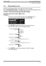
Changing Display Items

Select the screen display items for the type that you have selected.

Use

6. Initial Display Settings

in the

Type

menu to make the initial settings for when

the power is switched on and when you switch between types.

Refer to

5.3.9 Selecting Initial Display Settings

for details.

Switching order for the monitor display items
Procedure:

1.

Press

C

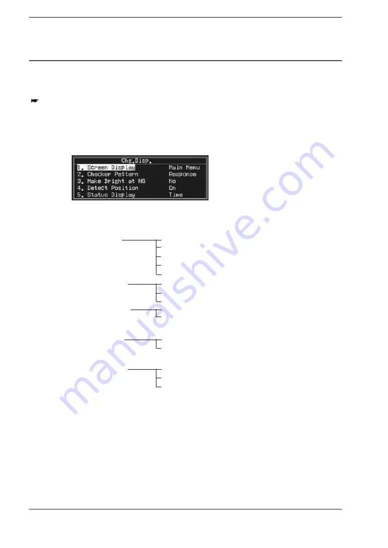
to open the Change Display menu (

Chg. Disp.

), and

then use the cursor lever to select the items for display.

2.

Press

ENTER

to display the selection menus for each item.

Use the cursor lever to select the display content.

1 Screen Display

Off
Main Menu
Data Monitor
Checker List
Spreadsheet

2 Checker Pattern

3 Make Bright at NG

*Fixed at No when the checker pattern display is set to off.

4 Detect Position

*Fixed at Off when the checker pattern display is set to Fixed.

5 Status Display

Off
Fixed
Response

Yes
No

Off
On

Off
Outputs
Time

3.

Press

ENTER

to confirm your selection. Press

C

to update

the monitor display.

Summary of Contents for A230

Page 1: ......

Page 2: ...re proper use There are two manuals available for this Micro Imagechecker A200 series 1 Micro Imagechecker A series Hardware Manual and 2 User s Manual Please read the manual appropriate for your needs Please ensure that the correct manual is read in accordance with objectives for use ...

Page 3: ...o user s injury or only property damage are assumed by mishandling of the product Do not dismantle or remodel the product It could cause excessive exothermic heat or smoke generation Do not touch the terminal while turning on electricity It could lead to an electric shock Do not allow foreign matters such as liquid flammable materials metals to go into the inside of the product It could cause exce...

Page 4: ...mmonia and caustic soda Static Electricity In a dry environment there is a risk of accumulation of static electricity so when there is a need to touch the equipment users should always discharge the accumulated static by touching an earthed part of the equipment first Cleaning Do not use thinners or similar solvents as they may dissolve parts of the unit and cause colors to run Power Use an insula...

Page 5: ...rial numbers other than those specified by Panasonic Industrial Devices SUNX Co Ltd will not be covered by the product warranty Do not disassemble modify or change internal settings for the Micro Imagechecker unit or other equipment Be aware that malfunctions damage destruction etc due to disassembly modification or use other than that described in the manual will not be covered by the product war...

Page 6: ......

Page 7: ...g Numerical Values 3 12 Chapter 4 Inspection Procedure 4 1 Before Starting an Inspection Checker Setting Procedure 4 3 4 2 IC Inspection Example 4 4 4 2 1 Character Verification Character Verification Checker 4 4 4 2 2 Inspection of No of Leads Pitch and Width Lead Inspection checker 4 6 4 2 3 Mark Detection Gray Scale Window Checker 4 9 4 3 Connector Inspection Example 4 12 4 3 1 Connector Dimens...

Page 8: ...ist 5 3 5 2 Environment Settings Environment settings common for all types 5 4 5 2 1 Menu screen 5 4 5 2 2 Camera 5 5 5 2 3 Start 5 6 5 2 4 Start Type 5 7 5 2 5 Communication 5 8 5 2 6 Display Setting 5 9 5 2 7 Save Image Mode 5 10 5 2 8 Initialize 5 12 5 3 Product Types 5 13 5 3 1 Menu Screen 5 13 5 3 2 Creating a New Product Type Number 5 15 5 3 3 Entering a Product Type Title 5 15 5 3 4 Set the...

Page 9: ... Adjustment that uses Matching 6 27 6 4 Position Adjustment Groups 6 31 Chapter 7 Character Recognition Dictionary and Character Recognition Function 7 1 About the Character Recognition 7 3 7 2 About the Dictionary 7 4 7 3 Procedure for Setting Character Recognition 7 5 7 4 Dictionary 7 6 7 4 1 Dictionary Configuration 7 6 7 4 2 Procedure for Setting the Dictionaries 7 7 7 4 3 Setting a Dictionary...

Page 10: ... Inspection Checker 10 1 About Lead Inspection Checkers 10 3 10 1 1 Lead Inspection Setting Menu 10 4 10 2 Set the Method for Lead Inspection 10 5 10 3 Set the Judgment Conditions 10 9 10 4 Select a Position Rotation Adjustment Checker 10 10 10 5 Viewing Inspection and Judgment Results 10 11 10 6 Copying and Deleting Lead Inspection Checkers 10 12 Chapter 11 Gray Scale Edge Checkers 11 1 Gray Scal...

Page 11: ... 20 13 4 1 About Judgment Output 13 20 13 4 2 Creating a Judgment Programme 13 24 13 4 3 Restrictions Applying to Judgments 13 27 13 4 4 Symbols Used by Judgment Programmes 13 28 13 5 Spreadsheets 13 29 13 6 Data Monitor 13 32 13 6 1 The Data Monitor Display 13 32 13 6 2 Data Monitor Display Setting Procedure 13 34 13 7 Checker List 13 37 Chapter 14 Save Data 14 1 Save Data 14 3 Chapter 15 Useful ...

Page 12: ... 5 2 Common setting items for serial and parallel 16 29 16 5 3 Product type switching using serial communication 16 30 16 5 4 Product type switching using parallel communication 16 31 16 5 5 Points of caution regarding product type switching 16 32 16 6 Character Recognition Change the Judgment String 16 33 16 6 1 Items Related to Serial Communication 16 33 16 6 2 Changing the Judgment String of Ch...

Page 13: ...and Minimum Limits 16 55 16 11Computer Link 16 56 16 11 1 Outline 16 56 16 11 2 Connection to a PLC 16 57 16 11 3 Communication 16 58 16 11 4 Communication Settings 16 60 Chapter 17 Vision Backup Tool Ver 2 17 1 Vision Backup Tool Ver 2 17 3 Chapter 18 Error Output 18 1 Error Processing 18 3 18 2 Error Signal Output Conditions Parallel 18 4 Chapter 19 The Setting Help Tools 19 1 Use Setting Help T...

Page 14: ...Table of Contents OCR Type A230 viii ...

Page 15: ...Chapter 1 Features of the A230 Character Recognition Type 1 1 Features of the A230 Character Recognition Type 1 3 ...

Page 16: ...Features of the A230 Character Recognition Type OCR Type A230 1 2 ...

Page 17: ...r strings are output serially Compares the recognized character string with String Judgment can be changed by the external device to determine whether it matches or not 01475B Character recognition For details see page 7 3 2 Allows easy character by character inspection Character Verification Checker See p 8 3 Checks for missing characters dirt blurring and incorrect characters on a character by c...

Page 18: ...f leads Pitch Width Check using the Lead Inspection Checker 4 You can use a Gray Scale Edge Detection Checker and Gray Scale Window Checker to measure the dimensions determine the orientation and detect missing leads See p 11 3 and 12 3 Measure the pitch using a Gray Scale Edge Checker Detect presence of the mark using a Gray Scale Window Checker 5 Use the Position Rotation Adjustment function to ...

Page 19: ...l calculation program and judgment conditions program to make a pass fail decision based on the inspection results See p 13 3 8 You can use input from external equipment to re register inspection reference characters or patterns and templates or switch products in accordance with the changes in the items to be inspected See p 16 29 16 34 and 16 41 9 Functions such as the Trap function NG Display f...

Page 20: ...Features of the A230 Character Recognition Type OCR Type A230 1 6 1 1 Features of the A230 Character Recognition Type ...

Page 21: ...Chapter 2 Outline of Functions 2 1 Outline of Functions 2 3 ...

Page 22: ...Outline of Functions OCR Type A230 2 2 ...

Page 23: ...ers or patterns against registered characters or patterns on a character by character basis or all together 8 3 The character image being used as the reference for the inspection can be re regis tered via input from external equipment 16 34 Smart Matching function This function finds target objects that match the image registered in the template It detects the number and position of the matches 9 ...

Page 24: ... calculation parameters The A230 can communicate with FP Series PLCs manufactured by Panasonic Industrial Devices SUNX Co Ltd without a program on the external device side using the Computer Link communication mode 16 5 Debugging Save Image function This function saves inspection images which can then be called up and tested again with different settings 15 3 NG Screen Display func tion If an NG N...

Page 25: ... 3 2 Keypad 3 5 3 2 1 Keypad 3 5 3 2 2 Operating the Cursor lever ENTER button 3 6 3 3 Main Screen Operations 3 7 3 3 1 Menu Selection 3 7 3 3 2 Switching the Image Displayed on the Monitor 3 8 3 3 3 Changing Display Items 3 9 3 4 Setting Numerical Values 3 12 ...

Page 26: ...Screens and Basic Operations OCR Type A230 3 2 ...

Page 27: ...r 4 Menu items 1 TYPE Allows you to make new type switch the type delete the type 2 CHECKER Allows you to set up various check function as well as Judgment Numerical calculation and Image data 3 DATA MONITOR Use to set the data displayed for data monitoring 4 SPREADSHEETS Shows the inspection calculation results in a table 5 CONVERSION DATA This function is used to replace the number of measured p...

Page 28: ...LP TOOLS Functions to adjust camera adjust lighting settings and check the connection for parallel communication 5 Keypad key functions Displays the keys and functions that can be used with the current menu 6 Image icon Displays the type of the currently displayed Image Press the B key to switch images Refer to 3 2 1 Keypad and 3 3 2 Switching the Image Displayed on the Monitor for details 7 Time ...

Page 29: ...hed to is displayed at the bottom of the screen Refer to 3 3 2 Switching the Image Displayed on the Monitor for details Camera A Gray Thru Camera A Gray Mem Camera A Gray NG A A N A Camera B Gray Thru Camera B Gray Mem Camera B Gray NG B B N B 3 C button This button is used for mode switching between the display non display of menus icons checker patterns and so on as well as for selecting menus e...

Page 30: ... move the cursor move the lever to the desired direction Up Down Left Right Up right Down right Down left Up left Operating the ENTER button To confirm i e enter input press the centre of the cursor lever Press straight downwards ENTER Note If you happen to press the ENTER button by accident while operating the cursor lever you may carry out an input operation by mistake To guard against this remo...

Page 31: ...or lever to select an item Use the cursor lever to select an item Use the cursor lever to select an item and press ENTER to confirm the selection ENTER C 2 CHECKER 2 CHAR VERIF 4 LEAD INSPECTION 5 GRAY EDGE DETECTION 6 GRAY WINDOW 3 SMART MATCHING 1 POS ROT ADJ 7 GROUP MOVE 8 NUMERICAL CALCULATION 9 JUDGMENT 10 IMAGE DATA 6 GRAY WINDOW 2 Checker Setting 4 Pos Rot Adj Group 5 Copy Checker 6 Delete ...

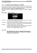
Page 32: ...setting A Gray Thru The image currently captured by the camera if you cover the camera lens with your hand the display will go dark Gray Mem An image that has previously been captured Inspections are performed using this memory image covering the lens does not change the image Gray NG A captured image same as a memory image An image that was inspected and produced results that were outside the ran...

Page 33: ... Procedure 1 Press C to open the Change Display menu Chg Disp and then use the cursor lever to select the items for display 2 Press ENTER to display the selection menus for each item Use the cursor lever to select the display content 1 Screen Display Off Main Menu Data Monitor Checker List Spreadsheet 2 Checker Pattern 3 Make Bright at NG Fixed at No when the checker pattern display is set to off ...

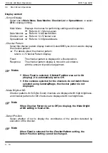
Page 34: ... displayed in a fixed position Response The checker pattern display is moved in accordance with the amount of position adjustment Notes When Fixed is selected if Detect Position was set to On display it is automatically set to Off If the cameras selected for the checkers do not match those selected using Camera Image the checker pattern is not displayed Make Bright at NG Checker patterns for NG No...

Page 35: ...splayed on the bottom of the screen Select Off to display nothing Outputs Displays the ON OFF status of the parallel output RDY ERR STR OVF and D1 to D8 Time Displays the time required for inspection This is the time for which the READY signal has been off R E S 1 2 3 4 5 6 7 8 ON output OFF RDY ready ERR error STR strobe OVF overflow D1 to D8 O ...

Page 36: ...ly incremented or decremented when appropriate The upper limit cannot be set to a value less than the lower limit and the lower limit cannot be set to a value higher than the upper limit In this situation using the cursor lever simply moves the highlighting to a different digit If you need to set the upper limit to a value less than the current lower limit first select the lower limit and reduce i...

Page 37: ... Mark Detection Gray Window Checker 4 9 4 3 Connector Inspection Example 4 12 4 3 1 Connector Dimension Measurement Gray Edge Checker 4 12 4 4 IC Inspection Example 4 15 4 4 1 Counting ICs Smart Matching checker 4 15 4 5 Displayed Image and Test Functions 4 18 4 6 Hiding Images and Menus 4 19 4 7 Checker Pattern Display 4 20 4 8 Specifying Position and Rotation Adjustment Group 4 22 4 9 Selecting ...

Page 38: ...g Method 4 26 4 11 1 Rectangle circle oval 4 26 4 11 2 Line 4 26 4 11 3 Polygon 4 27 4 12 Setting Masking 4 28 4 13 Filter Setup 4 29 4 14 Changing Shapes 4 30 4 15 Entering Upper and Lower Limit Values 4 31 4 16 Copying a Checker 4 32 4 17 Deleting a Checker 4 33 ...

Page 39: ...mple p 4 15 Create the checker Select a camera See 4 9 Selecting Camera p 4 23 Set the inspection method and conditions checker settings See 4 10 Area Setup and Out of Area Range p 4 24 4 11 Checker Area Setting Method p 4 26 Setting judgment conditions and processing conditions See 4 12 Setting Masking p 4 28 4 13 Filter Setup p 4 29 Settings for position rotation adjustment See 4 8 Specifying Po...

Page 40: ...Character Verification checker to inspect characters and numbers printed on the inspection target The Character Verification checker compares the characters on the inspection target with registered images to see if they are the same and thereby identify quality problems There are two types of inspection Character Verification character by character and Pattern Inspection comparison of multiple cha...

Page 41: ...segmentation conditions Item Description of Setting Area Encloses the region on the image for performing segmentation Segmentation Color Select the text color to be detected either black or white Segmentation Area Min Set this when you want to eliminate unwanted noise Background Process Set this when you want to eliminate unwanted noise Registered Image Allows you to check the registered character...

Page 42: ... Leads Pitch and Width Lead Inspection checker Use a Lead Inspection checker to inspect the number of leads on an IC or connector Counting the number of leads and measuring the width and pitch of the leads allows you to check for bent leads etc Refer to 10 Lead Inspection Checker for a detailed explanation about each item Inspect using the Lead Inspection Checker see p 10 3 for details In this exa...

Page 43: ...ne scan or Plane scan Direction Select either horizontal or vertical for the direction in the case of Plane scan only Area Specify the range to scan on the image Object Select whether the lead portion to be inspected is the black portion or the white portion In this example we will use the following settings 21 Shape 22 Area 23 Object White Line Start point Scan area End point Scan object White 4 ...

Page 44: ...ads 20 Width 2 0 to 3 5 Pitch 7 0 to 9 5 9 Press the A Test key to perform a test and confirm that the result is OK If it is not OK change the judgment conditions and continue to test until the result is OK Step 2 Perform an inspection Once you have registered a character image for use as a reference and set the scan method you can execute the Lead Inspection Checker 1 Return to the main menu and ...

Page 45: ...e whether or not it is acceptable With the checker you can check the average brightness value to determine whether or not the mark is present and its quality blurring etc Refer to 12 Gray Scale Window Checker for a detailed explanation of each item For inspection by the Gray Scale Window checker Refer to p 12 3 for details The mark to be inspected is the white part as shown in the diagram ...

Page 46: ...Gray Scale Window checker setting menu will appear 6 GRAY WINDOW Jud NG 22 Area 206 200 305 279 23 Mask Shape None 24 Mask Area No 1 Average 0 2 Checker Setting 21 Shape Rect 3 Select Checker Setting from the menu and set the scanning method for the inspection Item Description of Setting Shape Select the shape of the area to scan Area Specify the range to scan on the image Mask Shape Use this to s...

Page 47: ...article Item Value Average 42 6 Press the A Test key to perform a test and confirm that it is OK If it is not OK revise the judgment conditions and continue testing until you get an OK result Step 2 Perform an inspection Once you have set the judgment reference you can execute the Gray Window Checker 1 Return to the main menu and press the A Start key to perform an inspection on a new target objec...

Page 48: ...led explanation of each item Step 1 Measure the edge position of the part to be measured With a Gray Scale Edge checker you can measure the coordinates of the edges contours on an inspection target Inspection of the positional relationships is possible by setting a good article as a reference 1 Select a target object on which all of the connectors are present and straight and capture it on the cam...

Page 49: ... edge detection Condition Set this when you cannot detect an edge correctly Detect Position Select what part of the boundary that you want to detect as the edge front edge front edge and back edge maximum differential part with the greatest contrast or multiple all detected edges In this example we will use the following settings 24 Area 25 Edge Condition Both 26 Edge Thres Value 50 22 Direction H...

Page 50: ...aximum and minimum values for the dimension obtained here and perform judgment Refer to 13 3 Numerical Calculation for details regarding numerical calculations Step 3 Perform an inspection 1 Return to the main menu and press the A Start key to perform an inspection on a new target object The dimension is calculated based on the detection results of the Gray Scale Edge checker If you establish judg...

Page 51: ...Smart Matching checker to count a number of the same article Refer to 9 Smart Matching for a detailed explanation of the various setting items Step 1 Register a template image of the target object to be counted 1 Capture one of the articles to be counted on the camera 2 Select Checker Smart Matching Checker Setting from the menu The Smart Matching menu screen will appear 3 SMART MATCHING 24 Output...

Page 52: ...e The Smart Matching checker will search the area inside the marquee 5 Select Sequence and set the search conditions Searching is a five stage process You can set judgment conditions such as accuracy quantity and correlation for each stage If you want to count the number of articles set the number of articles that should be detected i e the quantity in the judgment conditions 6 Press the A Test ke...

Page 53: ...tep 2 Perform an inspection 1 Return to the main menu and press the A Start key to perform an inspection The number of articles detected inside the search area is displayed on the top right of the screen Template Matching 9 objects that match the template were detected ...

Page 54: ...ion judgment output and spreadsheets are not included in a test and there is no parallel or serial output The inspection time displayed represents only the time required to execute the checkers selected from the menu Note Test inspections are only performed to check how inspections run with particular settings and parameters For ordinary inspections we recommend that you input the start signal fro...

Page 55: ...firm a checker number the setup menu for each checker is displayed The Hide Image and Hide Menu functions are available only when you are working in this menu Use the cursor lever to toggle between displaying and hiding the image or the menu Hide image Hide menu Α Α While the image is suppressed a highlighted Hiding Image message is displayed In this state some functions including A Test B Image a...

Page 56: ...re displayed brightly unless Make Bright at NG is set to YES If Make Bright at NG is set to NO only the checker detecting the reject is displayed brightly No other checkers have a bright pattern display Drawing checker patterns Character Verification Displays the checker pattern detected character area and the part for which the comparison result was NG failed The rectangles on the characters indi...

Page 57: ...raight lines to mark the positions where edges were detected The straight lines are not displayed if no edge is found Example Gray scale edge checker pattern display Edge detected here Gray scale window checker Checker patterns are displayed Example Binary window checker pattern display Note When position adjustment is used the checker is displayed at a position that has been moved by the amount o...

Page 58: ...djuster group which has an angle of rotation an Area will be changed OK message is displayed Select Yes to change the group number The execution position angle of the checker adjusted for position or rotation will change at that point If you select No the group number will not change If the position and rotation adjustment group is specified before setting an area then when setting the area the im...

Page 59: ... setting for each checker to select scanning for the image captured by either camera A or Camera B If only one camera is connected or if the setting for the capture camera in the Type menu is something other than AB it is not possible to select anything but A otherwise an error message will be displayed ...

Page 60: ...es can be set in the range X 2 to 509 Y 2 to 477 If an attempt is made to set coordinates outside the range available a Position is out of image range error is displayed and the coordinates return to those before the change was attempted With the Character Verification Checker the allowed setting range depends on the value set for Background Process Refer to 7 Character Verification Checkers for d...

Page 61: ...of the area setting In some cases due to the next execution position and depending on the amount of correction area settings may not be possible even though they are inside the screen cases when the setting position cannot be set inside the screen In such cases the error message Position is out of image range is displayed If the error occurs when you are making area settings the area coordinates a...

Page 62: ...d the end point ENTER C ENTER C ENTER 4 11 2 Line Press ENTER to switch between Move all Move start point Move end point and Fix Press C to go in the opposite direction Use the cursor lever to move the whole area the start point and the end point ENTER C ENTER C ENTER Note When setting a line shape for position and rotation adjustment only a horizontal line can be set when the scanning direction i...

Page 63: ...ce adds an additional node and pressing A and B deletes a node Adding a node Use the cursor lever to move the added node then press ENTER to fix it Press C if you wish to cancel the addition and revert to Set node mode More nodes can be added up to a maximum of 16 Deleting a node Delete the selected node Nodes can be deleted until only the minimum three nodes remain ENTER C B A C B A C ENTER Selec...

Page 64: ... mask area and it does not fall within the above range it will go back to the setup position A checker that generates an error when moved outside the screen area by an adjuster when an inspection is performed has its checker pattern displayed at the position where it was set The area setting is then made by changing the area from this position The checker will be executed from the same position wh...

Page 65: ...ese filters work on a captured image performing dilation or erosion before inspection You can check enlarged and reduced images in the area setting screen for each checker Two levels of filtering 3 3 and 5 5 are available for both dilation and erosion filters working on a 3 pixel square or 5 pixel square relative to the original image Original image 5 5 erosion filter 3 3 erosion filter Original i...

Page 66: ...hole of the inspection area is included within the mask area The No serching area exists Changes can t be stored error message is displayed Move the area to the center of the screen before attempting the shape change again If an attempt is made to change a shape at the edge of the screen and the Position is out of image range message is displayed move the area to the centre of the screen before at...

Page 67: ...ker Example Judgment conditions The parameters for entering upper and lower limit values are normally displayed as in Max Min You can select which parameter you want to enter Max or Min and enter values 5 Pitch Judgment 510 9 0 0 3 Detect Judgment 128 4 Width Judgment 510 9 0 0 ENTER 5 Pitch Judgment 510 9 0 0 6 Pos Rot Adj Group 0 3 Detect Judgment 128 7 Result 4 Width Judgment 510 9 0 0 Area Jud...

Page 68: ... Only checker numbers that have already been set are displayed when you are selecting the copy source for the checker number If there are no source checkers an error message saying No checker for copying exists is displayed An error message is also displayed if there is not enough space for copying 4 A message saying Data exists in destination OK to overwrite is displayed Select and confirm Yes if...

Page 69: ... 2 Select Delete checker and confirm 3 A message saying Delete is displayed Select and confirm Yes if you want to delete or NO to cancel the deleting Note Note that all of the data that has been set for the specified checker number will be deleted when you execute Delete The checker number selection menu is displayed after deletion is complete ...

Page 70: ...Inspection Procedure OCR Type A230 4 34 4 17 Deleting a Checker ...

Page 71: ...5 9 5 2 7 Save Image Mode 5 10 5 2 8 Initialize 5 12 5 3 Product Types 5 13 5 3 1 Menu Screen 5 13 5 3 2 Creating a New Product Type Number 5 15 5 3 3 Entering a Product Type Title 5 15 5 3 4 Set the Capture Camera 5 16 5 3 5 Select the Camera Image 5 17 5 3 6 Switching Between Product Types 5 18 5 3 7 Copying a Product Type 5 18 5 3 8 Deleting a Product Type 5 19 5 3 9 Selecting Initial Display S...

Page 72: ...Environment and Product Type OCR Type A230 5 2 ...

Page 73: ... selection at power up and product type switching Environment 5 7 Camera image selection at power up and product type switching Product Type 5 17 Display item selection at power up and product type switching Product Type 5 20 Display settings Screen brightness setting Environment 5 9 p y g Display item selection at power up Product Type 5 20 Communication setti gs Serial parallel settings Environm...

Page 74: ...ce 4 Communication 5 Display Setting 3 Start Type No 1 6 Save Image Mode Manual TYPE 1 A B C Esc 1 Camera 1 Camera Set the camera mode and shutter speed 2 Start Set the inspection start method Once Manual Repeat or Auto Repeat 3 Start Type Set the number of the type that starts up when the power is turned on 4 Communication Set serial parallel or other communications 5 Display Setting Sets the scr...

Page 75: ... the setting for random shutter camera mode Use the ANM831 camera Shutter speeds between 1 120 to 1 20 000 are available Double Speed Random Field This is the setting for random shutter camera mode Use the ANM831 camera Shutter speeds between 1 120 to 1 20 000 are available Internal Synchronization mode Frame In this mode the camera uses internal synchronization It is compatible with composite vid...

Page 76: ... a start command is received from the serial interface a single inspection is performed Manual Repeat When A is pressed or if a start input is received from the parallel interface or a start command is received from the serial interface continuous repeated inspection commences until A is pressed again Inspection stops even if another start input is received from the parallel or serial interface Au...

Page 77: ...up select the type number you want to start up and select this item Note Note that if you set Last store type No the type number at the last point at which the data was saved is the active type number If you set No 1 No 1 will still start up even if there is no No 1 type data 31 Display Message This can only be displayed when Last store type No is set as the Start Type setting If you set Yes when ...

Page 78: ... Min 0 to 100ms 10ms units Set the minimum type switch time for switching using parallel or serial input Because the type switch time is extremely short this function can prove effective in cases when it is not possible to perform switch completion notification using the external device The initial setting is 0ms Example 1 Setting value 0ms READY signal OFF time switch time 2 Setting value switch ...

Page 79: ...the same this setting has no effect on actual inspection Select Image Dark when a bright whitish image is being displayed and the white menu text is difficult to read 52 Outside Region Value Displays the image rotated image minus the adjustment amount when displaying an area checker with a rotation adjustment amount The results of the rotation as well as areas outside the screen are displayed and ...

Page 80: ...t in the register set for Trap in Judgment is NG i e when the trap condition is established When the Save Image Mode is set to Trap processing is not interrupted even if the trap condition is established However if Overwrite is set to No processing is interrupted at the point when the limit for the number of images that can be saved is exceeded and the trap conditions are established and an error ...

Page 81: ...aved Save Limit The OCV checker can store up to 8 screen images When using both the A and B cameras be certain to store in two screen sets a maximum of 4 image sets can be stored It is not possible to delete stored images one at a time or switch them In addition it is not possible to specify the number under which an image is stored Note Stored images are lost under the following conditions When y...

Page 82: ...ings to the original factory settings The Language setting is not initialized even if you initialize so the currently displayed language remains the selected language Note If you change settings in the Environment menu select Save Data from the main menu and save Note that if the power is turned off and you have not saved your data the setting changes will be lost ...

Page 83: ...PE 1 TYPE 1 Input the type number Input any number in the range 1 to 32 If data has already been set for the number entered the appropriate settings are displayed If no data has been entered then only the product type number is displayed 1 Copy Type Copies the type data 2 Delete Type Deletes the type data 3 Input Type Title Allows you to enter a title for the type If you select Input Type Title th...

Page 84: ...of checkers set for all product types must not exceed 4096 1 1 The method for counting differs according to the checker Product types character recognition numerical calculations judgment outputs and simple spreadsheets Each is counted as one checker Position rotation adjustment gray edge reference Number of reference checkers 2 and 1 in the case that priority is specified For example the checker ...

Page 85: ...ection window shown below will be displayed Use the cursor lever to select and set characters You can input up to 16 characters for the title To delete a character that you have input move the cursor to Del Letter at the top right of the window and press ENTER this deletes one character 3 When you have completed input move the cursor to Input is Completed and press ENTER The title is displayed to ...

Page 86: ...rs set for camera A execute AB Horizontal Camera A captures the top half of the image and camera B captures the bottom half and the image is composed as a memory camera A image Only the checkers set for camera A execute Notes If you are only connecting one camera connect it to the Camera A port Capture errors may occur if you connect it to the Camera B port Only one internal synchronizing camera c...

Page 87: ...ne with the B button in the main menu are temporary settings that remain valid until the power is switched off or the type is changed The menus differ depending on the settings made in Capture Camera Capture Camera settings A AB Vertical AB Horizontal B AB Note Select either Mem Image or NG Image gray for inspection execution for Thru Image display regardless of whether the standard camera or the ...

Page 88: ... message is also not displayed if you set No 1 as the start type number When you switch types the execution results and trap setup conditions are cleared for all of the checkers However specific substitution results are not cleared In addition if you select a type number that has not been set up the type cannot be switched Select a type number that has been set up and switch the type 5 3 7 Copying...

Page 89: ...copied When the product type was copied the image data saved with the copy destination product type including those that are locked are all deleted When the product type was copied spreadsheets data for the number of scans with the copy destination product type data for the number of errors and OK and NG data are all reset to zero 5 3 8 Deleting a Product Type Procedure 1 Set the type number to be...

Page 90: ...t to set and confirm your selection to display the selection menus Refer to 3 3 3 Changing Display Items for details Use the cursor lever to select the display items 61ScreenDisplay Off Main Menu Data Monitor Checker List Spreadsheets 62 Checker Pattern 63 Make Bright at NG Fixed at No when the checker pattern display is set to off 64 Detect Position Fixed at Off when the checker pattern display i...

Page 91: ... this all the product data you have entered will be deleted Procedure 1 Select Initialize all Types and confirm 2 A message saying CAREFUL Type data will be lost OK is displayed Enter YES to delete all types Enter NO to go back without deleting Note After executing Initialize all Types if no product type is set you will not return to the main menu Enter a type number and press ENTER to set a type ...

Page 92: ...Environment and Product Type OCR Type A230 5 22 5 3 Product Types ...

Page 93: ... uses Gray Edge Detection 6 11 6 3 2 Setting a Horizontal Detection Rotation Adjustment Checker or a Vertical Detection Rotation Adjustment Checker that uses Gray Edge Detection 6 15 6 3 3 Setting One Checker Position Adjustment that uses Matching 6 19 6 3 4 Setting Theta Rotation Adjustment that uses Matching 6 23 6 3 5 Setting One Checker Rotation Adjustment and Two Checker Rotation Adjustment t...

Page 94: ...Position and Rotation Adjustment OCR Type A230 6 2 ...

Page 95: ... and rotation adjuster For instance for position adjustment it is not possible to use a binary edge checker for horizontal adjustment and a feature extractor for vertical adjustment 14 different position and rotation adjuster modes are available with different types of base checker and different methods of inspection TYPE 1 2 MATCHING 1 GRAY EDGE DETECTION 1 POS ROT ADJ No 1 Pos Adj Hor Det Rot Ad...

Page 96: ...ure of the two being possible There is no need to set both the horizontal and vertical base checkers if not required If only one is set the adjustment in that direction will be calculated If both checkers are set the order of priority can be specified Edge detection is performed in Front detection position mode The reference point is the intersection between vertical and horizontal lines passing t...

Page 97: ...horizontal checkers Shapes available are lines and planes with a mixture of the two being possible Since the amount of adjustment is calculated from the results of two base checkers the reference position cannot be set unless two checkers are set Edge detection is performed in Front detection position mode The reference point is the centre point of the coordinate obtained by checker 1 and the coor...

Page 98: ... is calculated from the results of two vertical checkers Shapes available are lines and planes with a mixture of the two being possible Since the amount of adjustment is calculated from the results of two base checkers the reference position cannot be set unless two checkers are set Edge detection is performed in Front detection position mode The reference point is the centre point of the coordina...

Page 99: ...t can be selected from a maximum of 5 detection results Reference point Detection point Matching checker Theta rotation adjustment The amount of adjustment X Y θ can be calculated from the results of using a single matching checker as the base checker The reference point is the detection position sought using matching and any one point can be selected from a maximum of 5 detection results The rota...

Page 100: ...must be moved and the line created by the two points detected when the command was executed Reference point θ Y X Matching checker Two checker rotation adjustment The amount of adjustment X Y θ can be calculated from the results of using two matching checkers as the base checkers Set each point from the detection results one point at a time as you wish and their midpoint will be the reference poin...

Page 101: ...rmined according to the result of the prioritized checker Checker setting Priority not specified Priority specified Priority to vertical adjustment Priority to horizontal adjustment Direction of misalignment Direction of misalignment Vertical position adjuster Horizontal position adjuster Horizontal position adjuster Vertical position adjuster Error Error Priority given to vertical adjustment Prio...

Page 102: ...ontal base checker has been set the display shows only the value for the X coordinate and if only a vertical base checker has been set the display shows only the value for the Y coordinate For position and rotation adjustment the angle is fixed and displayed as 0 and for rotation adjustment the reference angle is displayed The amount of adjustment for a direction which has not been set is fixed an...

Page 103: ...justment Checker that uses Gray Scale Edge Detection This explains how to use a Gray Scale Edge checker as an adjustment checker If you are unfamiliar with the operation of Gray Scale Edge checkers read chapter 10 Gray Scale Edge Checkers You can set horizontal and vertical checkers and it is possible to use them for adjustment on their own or together When using vertical and horizontal checkers t...

Page 104: ... Use these to create the checker and set items such as the scan conditions 4 Priority Use this to specify which checker result is to have priority as necessary either vertical or horizontal 5 Base Pos Execute a test to register the base point for adjustment 6 Pos Rot Adj Group Set which checker is to be used for adjustment in the case that you are using multiple settings for position and rotation ...

Page 105: ...rea 206 200 305 279 Gray Edge Pos Adj No 1 25 Scan Pitch 1 24 Edge Thres Value 50 23 Edge Condition Both 2 Horizontal Checker 26 Filter 3 27 Width 5 28 Average Area 5 21 Shape Plane Set each of the items For details regarding the settings refer to 10 Gray Scale Edge Checkers This same menu is displayed when you select Vertical Checker 5 Set the priority Specify whether the vertical or horizontal c...

Page 106: ... Select Camera 3 Vertical Checker 4 Priority No 2 Horizontal Checker Gray Edge Pos Adj No 1 7 Delete Checker A Test B Image C Esc 6 Pos Rot Adj Group 0 5 Base Pos 61 3 38 0 89 3 Detection coordinates and angle Note Press the B Image key to check the base position using the image Press the ENTER key to register the displayed coordinates and angle as the base position The adjustment amounts X Y and ...

Page 107: ...ou are unfamiliar with the operation of Gray Edge checkers read chapter 10 Gray Scale Edge Checkers The setting method for the two checker types is identical and you must set two checkers In this example we will perform the settings for a Horizontal Detection Rotation Adjustment Checker Procedure 1 Select the Position Rotation Adjustment checker number TYPE 1 2 MATCHING 1 GRAY EDGE DETECTION 1 POS...

Page 108: ...ting the Position Adjustment checker 2 Checker 1 3 Checker 2 Use these to create the checkers and set items such as the scan conditions 4 Base Execute a test to register the base point for adjustment 5 Pos Rot Adj Group Set which checker is to be used for adjustment in the case that you are using multiple settings for position and rotation adjustment Select a group number Refer to Position Adjustm...

Page 109: ...th checkers Select Checker 1 to display the Checker 1 setting menu 1 POS ROT ADJ 22 Area 206 200 305 279 Gray Edge Hor Det Rot No 1 25 Scan Pitch 1 24 Edge Thres Value 50 23 Edge Condition Both 2 Horizontal Checker 26 Filter 3 27 Width 5 28 Average Area 5 21 Shape Plane Set each of the items For details regarding the settings refer to 10 Gray Scale Edge Checkers This same menu is displayed when yo...

Page 110: ...ADJ Jud NG 1 Select Camera B 3 Checker 2 Empty 2 Checker 1 Gray Edge Hor Det Rot No 1 6 Delete Checker A B Image C Esc 5 Pos Rot Adj Group 0 4 Base Pos 61 3 380 0 89 3 Detection coordinates and angle Note Press the B Image key to check the base position using the image Press the ENTER key to register the displayed coordinates and angle as the base position The adjustment amounts X Y and θ are disp...

Page 111: ...use a Matching checker as an adjustment checker If you are unfamiliar with the operation of Matching checkers read chapter 8 Smart Matching Procedure 1 Select the Position Rotation Adjustment checker number TYPE 1 1 GRAY EDGE DETECTION 1 POS ROT ADJ No 1 2 MATCHING 2 Select MATCHING 1 POS ROT ADJ 22 Theta Rot Adj No 1 23 One Chkr Rot Adj 24 Two Chkr Rot Adj 21 One Chkr Pos Adj 2 MATCHING ...

Page 112: ...elect either the camera A or camera B image for operating the Position Adjustment checker 2 Checker Setting Use this to create the checker and set items such as the scan conditions 3 Base Pos Execute a test to register the base point for adjustment 4 Pos Rot Adj Group Set which checker is to be used for adjustment in the case that you are using multiple settings for position and rotation adjustmen...

Page 113: ...s No 1 22 Search Area 0 0 511 479 23 Sequence 2 Checker Setting 24 Output Unit No 25 Check Template 21 Template 21 Template 22 Search Area 23 Sequence 24 Output Unit 25 Check Template Set each of the items For details regarding the settings refer to 9 1 2 Checker Setting and 9 1 4 Check Template in 8 Smart Matching Note however there is no Rotation Setting in Sequence and no Theta setting in the S...

Page 114: ...1 3 Base Position No 2 3 4 5 1 Co X Co Y Theta Corre A Test B Pos Dsp C Esc 53 1 308 1 0 0 0 89 Select the appropriate position from the table and press the ENTER key The coordinates that you select are registered as the base position When you return to the setting menu the adjustment amounts X Y and θ are displayed at the top right of the screen Press the B key to check the base position using th...

Page 115: ... use a Matching checker as an adjustment checker If you are unfamiliar with the operation of Matching checkers read 8 Smart Matching Procedure 1 Select the Position Rotation Adjustment checker number TYPE 1 1 GRAY EDGE DETECTION 1 POS ROT ADJ No 1 2 MATCHING 2 Select MATCHING 1 POS ROT ADJ No 1 23 One Chkr Rot Adj 24 Two Chkr Rot Adj 21 One Chkr Pos Adj 2 MATCHING 22 Theta Rot Adj ...

Page 116: ...either the camera A or camera B image for operating the Position Adjustment checker 2 Checker Setting Use this to create the checker and set items such as the scan conditions 3 Base Pos Execute a test to register the base point for adjustment 4 Pos Rot Adj Group Set which checker is to be used for adjustment in the case that you are using multiple settings for position and rotation adjustment Sele...

Page 117: ...ay the setting menu 1 POS ROT ADJ Matching One Chkr Pos No 1 22 Search Area 0 0 511 479 23 Sequence 2 Checker Setting 24 Output Unit No 25 Check Template 21 Template 21 Template 22 Search Area 23 Sequence 24 Output Unit 25 Check Template Set each of the items For details regarding the settings refer to 9 1 2 Checker Settings and 9 1 4 Check Template in 8 Smart Matching ...

Page 118: ...1 3 Base Position No 2 3 4 5 1 Co X Co Y Theta Corre A Test B Pos Dsp C Esc 53 1 308 1 0 0 0 89 Select the appropriate position from the table and press the ENTER key The coordinates that you select are registered as the base position When you return to the setting menu the adjustment amounts X Y and θ are displayed at the top right of the screen Press the B key to check the base position using th...

Page 119: ...Smart Matching One Checker Rotation Adjustment uses one checker and Two Checker Rotation Adjustment uses two checkers With Two Checker Rotation Adjustment there are two types of checker settings but the setting method for each is the same as that for One Checker Rotation Adjustment Procedure 1 Select the Position Rotation Adjustment checker number TYPE 1 1 GRAY EDGE DETECTION 1 POS ROT ADJ No 1 2 ...

Page 120: ...or operating the Position Adjustment checker 2 Checker Setting Use this to create the checker and set items such as the scan conditions Note In the case of Two Checker Rotation Adjustment Checker 1 and Checker 2 are displayed 3 Base Pos Execute a test to register the base point for adjustment 4 Pos Rot Adj Group Set which checker is to be used for adjustment in the case that you are using multiple...

Page 121: ... No 1 22 Search Area 0 0 511 479 23 Sequence 2 Checker Setting 24 Output Unit No 25 Check Template 21 Template 21 Template 22 Search Area 23 Sequence 24 Output Unit 25 Check Template Set each of the items For details regarding the settings refer to 9 1 2 Checker Settings and 9 1 4 Check Template in 8 Smart Matching Note however there is no Rotation Setting in Sequence and no Theta setting in the S...

Page 122: ...rre 125 3 403 4 0 0 0 61 250 3 410 8 0 0 0 89 2 Select the appropriate position for base point 1 from the table and press the ENTER key The coordinates that you select are registered as the base point 1 position Switch to the Base Point 2 table and select the appropriate position for base point 2 from the table and press the ENTER key The coordinates that you select are registered as the base poin...

Page 123: ...mber When defining an inspection checker set the number of the position adjustment group to be used by highlighting the group number The initial value for the group number is 0 Notes If you are going to carry out position adjustment followed by a further position adjustment be sure to set the group number i e the position adjustment number corresponding to the adjustment The position will not be a...

Page 124: ...ed by the checkers Figure 1 Figure 2 Position adjustment 1 R1 G 1 R2 G 1 Movement Position adjustment 1 R1 G 1 R2 G 1 Example 2 Keeping the same checker settings as example 1 two workpieces of different dimensions are inspected See how the position adjustment group number affects the result when the length of the workpiece varies 1 Inspection using only one group group No 1 G 1 Because only a sing...

Page 125: ...justment 2 Position adjustment 1 Position adjustment 2 R1 G 1 R2 G 2 Example 3 If the position adjustment group No is 0 no adjustment is performed and the checker always inspects the same position Note If you find that the position is not adjusted despite having defined position adjustment checkers the cause may be that the inspection checker still has its group number set to 0 Consider examples 1...

Page 126: ...example below shows three position adjusters The numbers represent the position adjuster number set from the position adjustment menu If a displaced workpiece is then inspected the result differs according to the group number settings 1 When the position adjusters have all been set independently If the group numbers are all different or all set to 0 as shown below inspection will only be performed...

Page 127: ... Follow up Adjustment for Group No 1 Adjustment for Group No 2 Position adjustment No 2 Follow up Position adjustment No 3 No 2 is adjusted in accordance with the amount of movement of No 1 and No 3 is adjusted in accordance with the amount of movement of No 2 By setting the position adjustments in this way it is possible to have a position adjustment checker based on the results of an earlier pos...

Page 128: ...1 Create Position Rotation Adjustment checker No 1 2 Create a Gray Edge Vertical Detection Rotation Adjustment checker 3 Set the Reference checker area and conditions and set the base position TEST Position Rotation Adjustment checker No 1 Vertical Detection Rotation Adjustment Group No 0 4 Set Position Rotation Adjustment Group No 0 5 Create Position Rotation Adjustment checker No 2 6 Select Gray...

Page 129: ...ment checker No 2 Position Adjustment Group No 1 Character Verification checker No 1 Group No 1 11 Set Position Rotation Adjustment Group No 2 Upon execution Position Rotation Adjustment checker No 1 will execute and adjust Position Rotation Adjustment checker No 2 The adjustment amount of Position Rotation Adjustment checker No 2 will be used to adjust the Character Verification checker so that i...

Page 130: ...Position and Rotation Adjustment OCR Type A230 6 38 6 4 Position Adjustment Groups ...

Page 131: ...tting Character Recognition 7 5 7 4 Dictionary 7 6 7 4 1 Dictionary Configuration 7 6 7 4 2 Procedure for Setting the Dictionaries 7 7 7 4 3 Setting a Dictionary 7 8 7 4 4 Deleting a Dictionary 7 14 7 5 Recognizing Character 7 15 7 5 1 Procedure for Setting Character Recognition 7 16 7 5 2 Setting the Character Recognition Checker 7 17 7 5 3 Verifying the Result 7 24 ...

Page 132: ...Character Recognition Dictionary and Character Recognition Function OCR Type A230 7 2 ...

Page 133: ... registered in a dictionary beforehand and reads the label attached to the one in a dictionary in the highest match recognition values 1 checker can recognize up to 16 characters Character Recognition Checker can output the recognized character string using the serial port to the external devise In addition if you register a judgment character string beforehand this judges whether the recognized s...

Page 134: ...has five dictionaries that can only be used for the character recognition function and up to 40 characters can be registered in each OCR B font is registered in the Dictionary No 1 and OCR A font in the Dictionary No 2 at shipping from the factory User setting is available for all dictionaries Learning is done after the registration of the extracted letters or symbols the labeling Learning is requ...

Page 135: ...ont to be recognized into a dictionary and start the learning process 1 Set segmentation conditions 2 Register extracted characters to a dictionary 3 Dictionary learns what registered 2 Setting Character Recognition Conditions Set the character recognition checker 1 Set the segmentation conditions 2 Set the recognition conditions dictionary selection and recognition lower limits etc 3 Set judgment...

Page 136: ...ognition A230 has five dictionaries which can only be used for the character recognition function and up to 40 characters including symbols can be registered in each OCR B font is registered in Dictionary No 1 and OCR A font in Dictionary No 2 at shipping from the factory If these fonts are to be used no dictionary creation is required Dictionary No 1 OCR B font factory setting Dictionary No 2 OCR...

Page 137: ...g to the following procedure Flow 1 Segmentation 2 Registration Segmentation Color Dictionary registration Dictionary Check 0123456789 0 0 1 2 3 4 5 6 7 8 9 A B C D E F G H I J K L M N O P Q R S T U V W X Y Z Dictionary 3 Learning Learning Learning and additional learning Related parameters Finish Registered characters 9 1 3 2 45678 0 9 1 3 2 45678 Segmentation Condition ...

Page 138: ... characters to be extracted are lighter against a background select White 3 Segmentation Condition Set how to segment characters Select A Chg Disp key displays what extracted on the screen Adjust conditions while verifying it 41 Segmentation Area Min Set the segment area minimum values of what to be extracted This is useful for removing where NOT desired to be extracted such as noise etc Note The ...

Page 139: ...slice levels can be referred in Slice Level from the menu but can NOT be changed Gray The parameters for the segmentation are as follows 44 Thickness Thin Thick Select the width of the characters to be extracted 45 Noise Reduction 1 00 to 2 00 Set the level to delete the noise The default setting is 1 20 The higher level tends to remove the noise easily The lower level tends to extract the small c...

Page 140: ... Select the characters to be registered for labeling them and press the ENTER key The label selection screen appears 40 labels are available If a number or image is displayed in the box beneath the label it indicates that a letter or symbol has already been registered in that label 3 Select a lebel and press the ENTER key You can register 3 different images per label It does not matter which of th...

Page 141: ...steps 1 to 3 above for the number of characters you want to register If you registered 0 up to 9 one by one the registration screen changes as shown below The number in the box below the label indicates the number of images registered for that label up to 3 Press the A Chg Disp key to verify the registered image ...

Page 142: ...gly it can learn in a short time compared to the regular learning function A message below is displayed during learning Note If you do not execute the learning after having registered or changed the dictionary the message below will appear Press the C key to erase the message and then execute the learning function Be sure to conduct learning or additional learning when you have registered or edite...

Page 143: ...registered image Verifying a registered image 1 Select Dic Check 2 Select the label and pattern you want to verify The image registered in the selected label and pattern appears in the size registered Deleting a registered image 1 Select Dic Check 2 Select the label you want to delete 3 Highlight the pattern you want to delete and select B Delete ...

Page 144: ...step 3 When dictionaries 1 and 2 are selected 3 When dictionaries 1 and 2 are selected When all dictionaries are selected The following message is displayed Select YES to delete the content currently registered and return to the initial settings default settings at shipping What are the initial settings Returning to the initial settings means Dictionary No 1 is set back to OCR B font and Dictionar...

Page 145: ...ct Camera Checker Setting Area Segmentation Color Segmentation Direction Dictionary No Condition Segmentation Condition Separate No Yes Char Height Max Char Height Min Char Width Max Char Width Min Separate Level Filter Segmentation Method Slice Level Segment Area Min String Judgment Rec Lower Limit Output Control Pos Rot Adj Group Results Copy Checker Delete Checker ...

Page 146: ...er string Judgment character string Overall judgment judges to be OK if matches Output of Recognition character string String Judgment OutputControl Settings for the output using the serial port from Environment menu Recognition character string outputs using the serial port to the external device Individual judgment judges per each character whether recognition character matches with judgment cha...

Page 147: ...the area 2 Segmentation Color Select Black for segmenting characters darker against a background and White for segmenting characters lighter against a background 3 Segment Direction Select the segmentation direction according to the string direction When the string 1215A Note For separating Condition Separate only Left Right can be selected for the segmentation direction 4 Segmentation Condition S...

Page 148: ...ed are joined etc This is used for the characters connected to be extracted This is useful for recognizing the connected characters Execute the separation when the characters can NOT recognized well because they connect as shown in the figure below so that the recognition might be made LEI If the separation is executed I Separation processing Not executed LEI I LEI E L 251 Seperate Select Yes from...

Page 149: ...parated L is cut into pieces resulting in possibly miss recognizing as I and _ In that case select Low for the separate level 2 Setting the Recognition Conditions 1 Setting the dictionary number CHARA RECOG Checker setting Dictionary No Select among 1 to 5 the dictionary to be used The message below will be displayed Select YES so that the segmentation condition set in the dictionary registered is...

Page 150: ...etting screen is displayed As shown above with __ set for the maximum of 16 characters the overall judgment result or individual judgment result for each character will be OK regardless of whether characters were recognized or not and regardless of what those characters were if recognized If you intend to only output the recognized characters from the A230 and not to specify a judgment character s...

Page 151: ...cognition ranking is taken When both characters are numerals or symbols it is judged to be NG whereby recognition have been deemed not possible Out of the first or second character recognition ranking this takes the numeral 0 to 9 as the recognition result regardless of the recognition ranking When both characters are numerals the numeral with the first recognition ranking is taken When both chara...

Page 152: ...e only for those characters that are possible targets of recognition when you want to only output the verified character string and you do not specify a judgment character string Set this code only for those characters that are possible targets of recognition when you want to only output the recognized character string and you do not specify a judgment character string 4 Outputting Recognition Cha...

Page 153: ...with the blank Checker No Recognition character string Output 1 012 012 _ _ _ _0123456789C R 2 01234567890123 Remark When the number of characters exceeding the number of output characters is recognized the characters over the set number can not be output is output for the characters can not be recognized Settings for each Character Recognition Checker 1 Select Output Control Output control is use...

Page 154: ... NG Example of recognition character and judgment result When the number of the judgement character string is more than the number of recognition character string Judgement character string Character string to be read Recognition character Judgment 1215A 1215 1215 NG 1215_ 1215 1215 OK When the number of the judgement character string is less than the number of recognition character string Judgeme...

Page 155: ...esult 1 Select Result As shown the first and second character recognition rankings and their respective recognition values are displayed You can also display the result and recognition value for each recognition number Refer to the next step 2 Select the B Pos Dsp key The recognition result and values are displayed for each recognized character number Use the up down arrow keys to navigate the rec...

Page 156: ...Character Recognition Dictionary and Character Recognition Function OCR Type A230 7 26 7 5 Recognizing Character ...

Page 157: ...8 2 Pattern or Character Selection 8 7 8 3 Register the Reference Character Image Checker Setting 8 8 8 4 Setting the Process Conditions 8 13 8 5 Setting the Judgment Conditions 8 17 8 6 Selecting a Position Rotation Adjustment Checker 8 18 8 7 Viewing Inspection Results 8 19 8 8 Copying and Deleting Character Verification Checkers 8 20 ...

Page 158: ...Character Verification Checker OCR Type A230 8 2 ...

Page 159: ...as for character Registered Image Rotation Angle Delta Angle Threshold Filter Using the Character Verification function it is possible to extract information such as part numbers and lot numbers and verify their correctness It is also possible to check quantities and quality of marking defects and tone There are two types of character inspection you can inspect the characters one at a time or perf...

Page 160: ...stered as the reference character image for inspection Inspection involves comparing the characters on other articles to this reference character image An OK judgment depends on the results of the following two items 1 Whether or not the number of detected characters matches the number of registered characters 2 Whether or not the differential detection is smaller than the setting in 5 Sub Det Jud...

Page 161: ...orm position or rotation adjustment select a Position Rotation Adjustment checker 8 Press the A Test key to perform a character inspection and then confirm the result Register Inspect Operation Register character image Inspect reg istered image Character extraction Comparison inspection differential Differential result pro cessing Differential result refusal selection Judgment Related settings Che...

Page 162: ...he character to be used as the inspection reference 3 Condition Sets the character extraction conditions and inspection conditions and the process settings for the inspection result screen 4 Sub Det Area Sets the minimum area for groups of white pixels extracted by comparison subtraction to be treated as a target of judgment 5 Sub Det Judgment Sets the OK quantity for groups of white pixels extrac...

Page 163: ... time A maximum of 30 characters can be inspected at one time Check Registered image Inspection target OK OK NG Judgment NG Pattern Inspects multiple characters in a specified range at one time Check Registered image Inspection target C NG NG OK Note Once you select either Character or Pattern for the type of inspection you cannot change this setting If you want to change the setting from either C...

Page 164: ...1 Area 47 338 146 417 24 Background Process Low 26 Smart Setting No 27 Registered Image Procedure 1 Select Area from the menu and specify the segmentation range by enclosing it in a rectangular marquee Refer to 4 11 Checker Area Setting Method for details regarding area specification Note however depending of the setting value that you use in step 4 Background Process the range that can be specifi...

Page 165: ...duction level in the range 1 to 10 to fine tune the background processing Refer to Background Processing and Noise Reduction p 8 11 for details 6 It is possible to exempt the contour part of the segmented character from differential inspection attach a mask If variations in the thickness of lines in a character are affecting the checking results adjust the level of Smart Setting No Low Middle or H...

Page 166: ...sed for inspection reference select Registered Image In the case of character inspection In the case of pattern inspection If you are using Smart Setting and wish to check the mask press the B Mask key The area displayed as white is not subject to differential processing Note Smart Setting is performed with respect to the image displayed when segmentation is performed It is also performed on chara...

Page 167: ...rocedure and while checking the image Image to be deleted A B C A B C 1 Set the Background Process level to Low perform segmentation and check the image to see if the noise has been eliminated 2 If the noise is still present increase the Noise Reduction setting and then perform segmentation again and check whether or not the noise has been eliminated 3 If the noise is not eliminated even when you ...

Page 168: ... 24 24 487 455 Point Depending on the setting used for Background Process the setting range available for the Area setting changes If you set an area that exceeds these ranges one of the following messages will be displayed Area is off the screen Cannot modify or set or Setting position exceeds the range of movement If this happens correct the Area setting in accordance with the Background Process...

Page 169: ... 36 These settings set the conditions for detecting hereafter referred to as searching the position of a character pattern based on the image hereafter referred to as the Template Image registered using Checker Settings The basic search sequence is that same as that for the Smart Matching Checker The search is divided into a number of steps using different compression ratios within the template im...

Page 170: ... the range to search for each character By setting a wider search area you can avoid missed inspections due to shifted character position Notes When you increase the search do not enclose the neighboring characters The greater the size of the search area the longer is takes to process Search area Normal setting Poor setting ...

Page 171: ...sult Correlation minimum The correlation value is a numerical indicator of the degree to which the target matches the reference image If you cannot extract characters that should be acceptable make the correlation minimum Cor Min smaller If you are extracting unwanted noise make the correlation minimum Cor Min larger Template Contrast Used to make the settings for the template image to be used for...

Page 172: ... threshold value it s possible to extract missing parts only as white pixels and to extract parts with different brightness as white pixels Registered character image Gray value 200 Inspection character Gray value 140 Threshold value 100 Backgroundgray value 30 Extract parts that have a difference in gray value of 100 or more i e only extract the missing part Extract parts that have a difference i...

Page 173: ...ifferential of the registered image and the target image to be subject to the setting in Sub Det Judgment Pixel groups with areas smaller than the setting are not counted Sub Det Judgment With this you can set the quantity of the number of extracted pixel groups differential detection number that result from comparison differential of the registered image and the target image for an article to be ...

Page 174: ...ecker you can automatically correct for shifting of the target and correctly perform inspection In order to perform position and or rotation adjustment you must set the Position Rotation Adjustment checkers before setting the Character Verification checker Refer to 6 Position and Rotation Adjustment for details Select Pos Rot Adj Group from the CHAR VERIF menu and select the number of the previous...

Page 175: ...0 No 1 Character No Det Pos Corre Sub 2 3 4 5 1 X Y Sub Det Max Area 68 0 379 4 108 4 146 5 184 5 223 0 379 8 378 8 378 9 378 9 1 00 0 99 1 00 1 00 1 00 1 5 0 0 0 1 2 0 0 0 Up Down Press the B Pos Dsp key to observe the detected image while checking the inspection results The items displayed in Result number of detected characters detection position X Y correlation value Sub Det and Max Area can b...

Page 176: ... the Character Verification checker number 3 Select Copy Checker from the menu If no checkers have been set the message No checker available to copy is displayed 4 Select the number of the checker that you want to copy 5 The message Overwrite existing data will appear Select YES to copy or NO to abort the copy operation Delete a Character Verification checker Use the following procedure to delete ...

Page 177: ...ter 9 Smart Matching 9 1 Smart Matching 9 3 9 1 1 Menu Screen 9 3 9 1 2 Checker Settings 9 4 9 1 3 Subtraction Settings 9 10 9 1 4 Check Template 9 15 9 1 5 Result 9 16 9 2 Smart Matching Checker Setup 9 17 ...

Page 178: ...Smart Matching OCR Type A230 9 2 ...

Page 179: ...No Set the number of the matching checker to be created 1 Select Camera Select which camera A or B will supply the image on which the smart matching checker is to be activated 2 Checker Setting Create the matching checker and set the checker conditions 3 Subtraction Setting Set the parameters for the subtraction settings 4 Position and Rotation Adjustment Group Set which position and rotation adju...

Page 180: ...et the point in the centre of the area 22 Search Area Set the search area in the photographed image The checker will detect objects that resemble the template within the search area Note The search area can be set as a square area using the cursor lever but since setting the entire range of the photographed image as the search area will slow down the image processing please set the search area as ...

Page 181: ...t will be set at 8 pixels 4 pixels and sub pixels Once you set a step at an accuracy of 1 pixel or sub pixels additional steps cannot be set For example if you set the 3rd step at 1 pixel or sub pixels you cannot set the 4th and 5th steps Judgment conditions Judgment Number Cnt Set the upper limit of the number of detected objects The checker will detect a number of objects similar to the template...

Page 182: ...e range Angle After an object has been detected based on the correlation value the Imagechecker rotates the template within the angle range set in the rotation settings 30 and detects the object s rotation angle Accuracy Acc Set the minimum unit for rotating the template when performing angle detection Use the cursor lever to select the angle to one decimal place The Imagechecker rotates the templ...

Page 183: ...Smart Matching OCR Type A230 9 7 9 1 Smart Matching Example When no rotation angle is set angle range 0 3 Example When a rotation angle is set angle range 10 accuracy 1 3 ...

Page 184: ... but the image processing will take some time Thus to process the image quickly but without compromising accuracy try using different settings to adjust the image compression rate so that the Imagechecker can search the template image most effectively The search is performed in five steps In the 1st step 16 pixels the Imagechecker will search for images that are roughly similar to the sample image...

Page 185: ...and confirming the final search accuracy Since it is possible to set the correlation values judgment lower limits independently in each search step we recommend setting them up separately to suit the step The image compression can be set from 16 pixels but if the size of the set template does not fulfill that condition there may be conditions under which the search accuracy cannot be set 24 Output...

Page 186: ...ng the gray scale difference between the template and detected area into black and white The threshold value can be set in the range 0 to 255 34 Filter Once the gray scale image has been binarized it is possible to use various filters to effectively eliminate noise outside of the target image and to connect and separate objects See 4 13 Filter setup for details on filters 35 Deviation Set whether ...

Page 187: ...ce in brightness between the search image f x y and the template g x y If the absolute value of the difference is larger than the threshold level th the result will be 1 if it is smaller the result will be 0 It will search for the number of pixels where the result is 1 to find the area size S of the differential and will output that number as the result It can perform the same filter processing as...

Page 188: ...ts below the threshold value By doing this the corresponding portion will appear as the final results of the binarization Deviation data is set for each pixel in the template As shown in the diagram below with subtraction processing alone differences in the outline areas difference 128 threshold value 96 are recognized as black parts in the second row but if deviation data is also used the results...

Page 189: ...ng Subtraction calculations Deviation difference Threshold value 96 Binarization OK NG NG 128 128 96 Final result Deviation differentiation result Subtraction result Search image Deviation difference threshold value Deviation difference threshold value ...

Page 190: ... calculating deviation data is shown below New deviation threshold value difference in brightness Subtruction result Diviation data Diviations 0 75 Threshold value 96 Difference 128 Diviation calculations Thresholdvalue difference Diviations 1 0 Use the cursor keys to select the results to be used in updating the deviation data then press ENTER A message will appear Select Yes to update data or No...

Page 191: ...ou can verify the set template image and the compressed image being processed Display the set template image by selecting Check Template and then Template Verify the search area compressed image and the template compressed image by selecting Check Template and then Middle Step ...

Page 192: ... detected object and the correlated value 3 Display the detect point of the detected object by pressing B while the results are displayed When there is more than one detected object switch between them moving the cursor lever up and down A Test Execute a test B Pos Dsp Display a representation of the image you took C Esc Return to the previous menu ...

Page 193: ...tput conditions are set 9 Enter subtraction settings if necessary From Subtraction select Yes 10 Set the subtracted area judgment Set the upper limit value for the area of detected pixels from the subtraction result the number of pixels up to which the result is OK 11 Set the subtraction threshold value Set the threshold value that will be applied when performing binary processing on the gray scal...

Page 194: ...Smart Matching OCR Type A230 9 18 9 2 Smart Matching Checker Setup ...

Page 195: ...1 Lead Inspection Setting Menu 10 4 10 2 Set the Method for Lead Inspection 10 5 10 3 Set the Judgment Conditions 10 9 10 4 Select a Position Rotation Adjustment Checker 10 10 10 5 Viewing Inspection and Judgment Results 10 11 10 6 Copying and Deleting Lead Inspection Checkers 10 12 ...

Page 196: ...Lead Inspection Checker OCR Type A230 10 2 ...

Page 197: ...ese parameters You can set up to a maximum of 32 Lead Inspection checkers for each product type Number of leads Width Pitch The procedure for using Lead Inspection checkers is as follows 1 Select LEAD INSPECTION from the menu 2 Specify a number for the Lead Inspection checker 3 If there are two cameras connected select either camera A or camera B for performing the inspection 4 Specify inspection ...

Page 198: ...s relating to the lead inspection method 3 Detect Judgment Specify the number of leads for an OK result in the case that you will perform judgment based on the number of leads 4 Width Judgment Specify the lead width for an OK result in the case that you will perform judgment based on the lead width 5 Pitch Judgment Specify the Pitch for an OK result in the case that you will perform judgment based...

Page 199: ...irection when your selection for Shape was Line 3 Select Area and specify the inspection range The specification method differs depending on whether you selected Line or Plane for the Shape setting Refer to 4 11 Checker Area Setting Method for details regarding specifying the area in the case of a plane scan 4 Select Object and select either White or Black for the color of the objects to be detect...

Page 200: ...Average Area 5 261 Scan Pitch 1 Scan Pitch This sets the number of pixels for the scanning interval with respect to the scan direction in the inspection area The initial default value is 1 Setting a wide pitch makes inspection faster but there is a greater interval between the sections examined If the pitch is set wider than the scanning area only a single line is scanned Scanning direction Scanni...

Page 201: ...range for averaging starting from the edge position that satisfies the Filter Width conditions to the setting in Average Area and allows intervals between protrusions to be detected as edges Position where Width 6 is satisfied Scanning direction Average value 0 Average value 1 Average value 2 Average value 3 ...

Page 202: ...er Width settings X edge position No of edges Direction for counting the number of edges Scanning direction No of edges Count for the number of edges detected for each scan line No of edges No of edges No of edges No of edges In the above example with Filter 2 and width 7 the 6th column is detected ...

Page 203: ...um limits for the width of the leads An OK result is produced if the width is between these limits Perform an inspection on a good article to obtain the width value use the Result item to verify the value and use this value as an aid in setting the limits refer to the following page Pitch Judgment Set maximum and minimum limits for the lead pitch An OK result is produced if the pitch is between th...

Page 204: ...u can automatically correct for shifting of the target and correctly perform inspection In order to perform position and or rotation adjustment you must set the Position Rotation Adjustment checkers before setting the Lead Inspection checker Refer to 6 Position and Rotation Adjustment for details Select Pos Rot Adj Group from the LEAD INSPECTION menu and select the number of the previously set Pos...

Page 205: ...alues when setting the judgment and process conditions A Test B Pos Dsp C Esc No 2 3 4 1 10 2 13 9 11 3 13 9 17 0 21 7 15 1 0 0 174 148 196 117 162 199 168 177 Up Down 4 LEADINSPECTION Detected NG Cnt 4 No 1 Width OK Pitch OK Width Pitch Diff Front Rear Press the B Pos Dsp key to verify the results while displaying the inspected image 60 Rear Diff value 60 Front Diff value 55 Width 2 2 Pitch 7 5 C...

Page 206: ... Inspection checker number 3 Select Copy Checker from the menu If no checkers have been set the message No checker available to copy is displayed 4 Select the number of the checker that you want to copy 5 The message Overwrite existing data will appear Select YES to copy or NO to abort the copy operation Delete a Lead Inspection checker Use the following procedure to delete all settings for a Lead...

Page 207: ...Chapter 11 Gray Scale Edge Checkers 11 1 Gray Scale Edge Checkers 11 3 11 1 1 Menu Screen 11 3 11 1 2 Checker Setting 11 4 11 1 3 Result 11 11 11 2 Gray Scale Edge Checker Setup 11 13 ...

Page 208: ...Gray Scale Edge Checkers OCR Type A230 11 2 ...

Page 209: ...pe 11 1 1 Menu Screen 5 No Checker No Set the number of the gray scale edge checker to be created 1 Select Camera Select which camera A or B will supply the image on which the gray scale edge checker is to be activated 2 Checker Setting Set the checking area and set parameters etc 3 Detected Judgment Set the upper and lower limits for the number of edges detected by the gray scale edge checker and...

Page 210: ...t parameters etc 5 21 Shape Select the shape for the checker area 22 Direction Select the scanning direction for the checker being created This parameter is not displayed when line scanning is selected 23 Scan Method Select the scan method for the checker being created This parameter is not displayed when line scanning is selected ...

Page 211: ...t Single scanning A method of edge detection where the inspection area is scanned horizontally for each individual pixel in the scanning direction Scanning is performed according to four parameters scan pitch filter width and average area and it is relatively unaffected by noise enabling reliable edge detection Projection scanning Projection scanning is a method for images where the gray scale ima...

Page 212: ...on Point Scan direction Detection direction horizontal Detection direction vertical Finishing point Dark light Light dark Starting point Scan direction Detected Detected Detected Detected Detected Detected Dark light Light dark Starting point Finishing point Both Both 26 Edge Threshold Value Set the edge threshold values for the checker being created A gray scale edge checker performs differential...

Page 213: ...the sections examined If the pitch is set wider than the scanning area only a single line is scanned Scan pitch 1 Scan pitch 2 Scanning direction Scanning direction 272 Filter The filter function is a function that combines and makes one edge if the interval between pixels where an edge was detected relative to the scanning direction is less than the filter value 273 Width can only be set for indi...

Page 214: ...oint X Edge position Number of edges Number of edges Number of edges Number of edges Direction of the scan Direction for counting number of edges Number of edges count of edges detected for each individual scan line In the above example with Filter 2 and width 7 the 6th column is detected ...

Page 215: ...Checkers 274 Average Area can only be set for individual scans Set the range for averaging starting from the edge position that fulfills the filter width conditions Average 0 Average 1 Average 2 Average 3 The position where WIDTH 6 is satisfied Direction of the scan ...

Page 216: ...tial values Light Dark Method Display output coordinates Differential value Edge count Output Front 60 Differential value at point A 1 Point A output Front Rear 60 Differential value at point A 75 Differential value at point F 6 Points A and F output Peak 80 Differential value at point E 1 Point E output Plural Differential values for individual edge positions 6 Points A B C D E and F output ...

Page 217: ...A Test In camera mode Captures an image from the camera and inspects it In memory mode Inspects a current memory image without capturing a new imagefrom the camera Displays the results after inspection B Pos Dsp After deleting the display of results Displays the detected edge position and the edge data coordinates and differential value Pressing C returns to the display of results C Esc Pressing C...

Page 218: ...displayed B Disp All Display the positions of all the edges detected as a pattern C Esc Pressing C returns to the display of results Prev Displays the edge immediately prior to the one currently being displayed Next Displays the edge immediately following the one currently being displayed C Esc Pressing C returns to the previous checker setting menu ...

Page 219: ...ection area See 4 11 Checker Area Setting Method for details of how to set the area Note If the length of the X coordinate if a horizontal scan or the Y coordinate if a vertical scan is less than 12 pixels the area of the gray value edge checker cannot be set 8 From Edge Condition select whether to detect edges as differential value changes from light to dark or dark to light or both 9 At Edge Thr...

Page 220: ...Gray Scale Edge Checkers OCR Type A230 11 14 11 2 Gray Scale Edge Checker Setup ...

Page 221: ...Chapter 12 Gray Scale Window Checkers 12 1 Gray Scale Window Checkers 12 3 12 1 1 Menu Screen 12 3 12 1 2 Checker Setting 12 4 12 2 Gray Scale Window Checker Setup 12 5 ...

Page 222: ...Gray Scale Window Checkers OCR Type A230 12 2 ...

Page 223: ...Screen 6 No Checker No Set the number of the gray scale window checker to be created 1 Select camera Select which camera A or B will supply the image on which the gray scale window checker is to be activated 2 Checker Setting Create the check area and set parameters etc 3 Average Judgment If the average gray scale value in the inspection area is within the upper and lower limits it is judged to be...

Page 224: ...the data from an existing checker 6 Delete Checker Delete the checker Judgment Shows whether or not the value is within the average gray scale value limits Average The average gray scale value detected is displayed 12 1 2 Checker Setting Create the check area and set parameters etc 6 21 Shape Select the shape for the checker area 22 Area Create or move the checker area 23 Mask Shape Select the sha...

Page 225: ...te Circular elliptical areas must be set so that the difference between the X coordinate start point and end point is an odd number of pixels 5 Set the mask area to rectangle circle or polygon from Mask Shape 6 From Mask Area set the coordinates for the mask area See 4 12 Setting Masking for details of how to set the mask area 7 From Average Judgment set the upper and lower limits for average gray...

Page 226: ...Gray Scale Window Checkers OCR Type A230 12 6 12 2 Gray Scale Window Checker Setup ...

Page 227: ... 13 13 13 3 3 Restrictions Applying to Numerical Calculations 13 17 13 3 4 Symbols Used by Numerical Calculation Programmes 13 19 13 4 Judgment Output 13 20 13 4 1 About Judgment Output 13 20 13 4 2 Creating a Judgment Programme 13 24 13 4 3 Restrictions Applying to Judgments 13 27 13 4 4 Symbols Used by Judgment Programmes 13 28 13 5 Spreadsheets 13 29 13 6 Data Monitor 13 32 13 6 1 The Data Moni...

Page 228: ...Inspection Results and Output OCR Type A230 13 2 ...

Page 229: ...ipment and to perform numerical calculations on the results and create judgment programs to judge the results Inspection result Checker screen displays Spreadsheet Data Monitor Checker List Judgment Output Numerical Calculation Program See the relevant checker chapter Numerical value or OK NG Numerical value or OK NG OK NG ER OK NG Judgment Condition Program Display Output Conversion data 13 2 13 ...

Page 230: ...ns Specify this number when you wish to use the conversion data in a formula 2 Reference Distance Input the actual dimension measured on the screen using a scale or calipers that is to be used for the reference distance Input a number of up to seven digits 1 to 9999999 3 Pixels Measure the reference distance and input the number of pixels Input a number of up to seven digits 1 to 9999999 4 Scale W...

Page 231: ... press ENTER First input the distance between the scale measurement gradations as the Reference Distance 3 Next input the number of pixels between the scale measurement gradations obtained in step 1 4 When you finish inputting the number of reference pixels the scale factor is calculated automatically Note The four sets of conversion data set in CV01 to CV04 reference distance number of pixels and...

Page 232: ...r No The register setting No CA01 to CA32 for numerical calculation programmes These are displayed four at a time Move the cursor lever left or right to display the previous or following four registers 2 1 Calculation result Displays the result of the numerical calculation 2 2 Calculation result Displays the result of the numerical calculation However if the result exceeds eight digits is displaye...

Page 233: ...m Limits for Numerical calculations for details 5 Programmes Displays the set calculation programme A numerical calculation program can be up to 55 characters in length and up to 12 items can be set Example BW01 50 7 characters 2 items 6 Data Bit Sets the data length for when you will output numerical calculation results using parallel output 7 Start Press A to capture a new image and perform an i...

Page 234: ...External output registers that are not set are skipped during output Output data length Output port output pin No 8 bit data d8 d1 D8 D7 output pin No D6 D5 D4 D3 D2 D1 d1 d2 d3 d4 d5 d6 d7 d8 d16 d1 16 bit data D8 D7 D6 D5 D4 D3 D2 D1 d1 d2 d3 d4 d5 d6 d7 d8 d9 d10 d11 d12 d13 d14 d15 d16 output pin No d32 d1 32 bit data D8 D7 D6 D5 D4 D3 D2 D1 d1 d2 d3 d4 d5 d6 d7 d8 d9 d10 d11 d12 d13 d14 d15 d...

Page 235: ...Canceling Output Control Example 1 CA01 X direction distance CA02 Y direction distance CA03 angle calculated using CA01 and CA02 When using several formulas to calculate the final result an angle in the case above you can use this function to output the final result only Example 2 XCA01 X direction distance output suppressed XCA02 Y direction distance output suppressed CA03 angle calculated using ...

Page 236: ...t executed when there is no ACK signal input from the parallel input When the specific substitution flag is off the calculation is not executed and the previous value is retained OFF ON READY output READY START input START ACK Specific substitution Execute Execute Whether or not the specific substitution calculation is executed is determined by whether or not the ACK signal remains ON from before ...

Page 237: ...scale edge mode The Detection No that can be referenced is restricted according to the Detect Position mode Front Only Detection No 1 can be specified Front Rear Only Detection No 1 and No 2 can be specified Peak Only Detection No 1 can be specified Plural Not restricted No 01 to 99 ...

Page 238: ...ates of the locations in the diagram detected by a gray scale edge checker can be used with the Root Distance T and Atan functions to calculate the angle θ and the length of each side X1 Y1 X2 Y2 a b c θ Side a CA01 X2 X1 Side b CA02 Y2 Y1 Side c Using the Root function CA03 CA01 CA01 CA02 CA02 Pythagoras s theorem Using the Distance T function CA03 CA01TCA02 In both cases the result is output mul...

Page 239: ...culation programme you are going to create 8 NUMERICAL CALCULATION Max 0 Min 0 Result 0 Program 0 Result Jud OK CA01 CA04 CA01 Data Bit CA01 CA04 8bit 16bit 32bit A OutpContr B Delete C Esc 2 From the state shown in step 1 above press ENTER again A sub window is displayed for selection of parameters to be input 8 NUMERICAL CALCULATION Max 0 Min 0 Result 0 Program 0 Result Jud OK CA01 CA04 CA01 Dat...

Page 240: ...sult 0 Program 0 Result Jud OK CA04 CA01 Det No 2 1 Item 1 Co X Data Bit CA01 CA04 8bit 16bit 32bit CA01 GE02011 Next PA CH SM LD GE GW CA OCA QS CV Num Ope Max 0 Min 0 Result 0 Program 0 Result Jud OK CA04 CA01 CA01 GE02011 Data Bit CA01 CA04 8bit 16bit 32bit Max 0 Min 0 Result 0 Program 0 Result Jud OK CA04 CA01 CA01 GE02011 GE01011 Data Bit CA01 CA04 8bit 16bit 32bit Next PA CH SM LD GE GW CA O...

Page 241: ... Jud OK CA04 CA01 GE02011 GE01011 Data Bit CA01 CA04 8bit 16bit 32bit Next PA CH SM LD GE GW CA OCA QS CV Num Ope 0000000100 CA01 GE02011 GE01011 Set the maximum and minimum values Max Min 50 Result 0 Program 0 Result Jud OK CA04 CA01 GE02011 GE01011 Data Bit CA01 CA04 100 CA02 CA03 8bit 16bit 32bit To Revise a Programme During Input Procedure 1 Set the numerical calculation programme register No ...

Page 242: ...s displayed at the left of the register No XCA01 GE02011 GE01011 3 If a register has been specified for output control but you want to change the setting so that it can be output move the highlight cursor to any location other than then press A again and the X mark disappears enabling numerical calculation output for that programme CA01 GE02011 GE01011 Even if a formula is set and the Serial Outpu...

Page 243: ...merical calculations can operate on numbers in the range 2147483648 to 2147483647 Constants can be specified in the range 65535 to 65535 If an overflow if the number exceeds the permissible range occurs during calculation an error output is output from the parallel port at that point If the final result of numerical calculation is outside the range 2147483648 to 2147483647 then an error output is ...

Page 244: ...ficient of conversion data into the calculation When coefficient of conversion data is incorporate into a calculation the A210 actually performs calculation as follows CA01 A CV11 A Base distance Base pixels In the calculation above if A Base distance exceeds the values that can be used for the numeric calculation 231 to 231 1 an ERROR signal will be output This is because overflow error occurs an...

Page 245: ...correlation value Smart matching SM 01 to 4 2 nth X coordinate Smart matching SM 01 to 4 01 to 64 3 nth Y coordinate 4 nth theta angle 10 5 nth subtraction area 01 0 No of detections LeadInspection LD 01 to 32 01 to 99 1 nth lead width 10 p 01 to 99 2 nth pitch 10 G S l 01 0 No of detections Gray Scale Edge GE 01 to 32 01 to 99 1 nth X coordinate Edge 01 to 99 2 nth Y coordinate Gray Scale Window ...

Page 246: ...6 JD07 JD08 3 1 2 JD01 1 Output register No Specify which output register the results of judgment are output from There are two different types of judgment output registers internal judgment registers R and registers for external output D You can set up to 32 registers for the A220 and up to 8 registers for the A100 Only 8 registers can be shown on screen at a time but the screen can be scrolled w...

Page 247: ...hecker CA numerical calculation OCA previous numerical calculation result JR judgment output R register JD judgment output D register Operators The following operators are used Symbol Reading Name Content OR Inclusive OR When either of the results is 1 the result output is 1 AND AND When both of the results are 1 the result output is 1 XOR Exclusive OR When the two results are different the result...

Page 248: ...the next inspection can be performed is to press B 2 If Save Image Data in the Environment menu is also set for the Trap function in addition to the settings for 1 the memory image at the time the NG occurs is stored See 15 1 Loading and Saving Image Data for details Unlike 1 the READY signal stays on so it is possible to continue performing inspections after a NG is generated 2 NG Display functio...

Page 249: ...1 OK OK Capture image NG2 Hold OK Capture image Capture image Capture image Capture image Hold NG image 1 NG image 1 NG image 2 It is also possible to set and change checkers when a NG image is being displayed However in the following cases the NG display image is reset The B button is pressed to switch display images The product type is switched The power is switched off ...

Page 250: ...gister number for the calculation programme you are going to create and press ENTER 9 JUDGMENT Program Jud JD02 JD03 JD04 JD05 JD06 JD07 JD08 JD01 JD01 2 From the state shown in step 1 above press ENTER again A sub window is displayed for selection of parameters to be input Note This cannot be selected if no PA CR CH SM LD GE GW CA or OCA JR JD checker data exists 3 Next select the parameters to b...

Page 251: ...r then after setting the judgment programme register No use the cursor lever to move the highlight cursor to the incorrect item and press B to delete the item JD01 CH0100 Program Jud JD02 JD03 JD04 JD05 JD06 JD07 JD08 JD01 JD01 2 To add to a programme characters are inserted in front of the highlight cursor To Delete Judgment Conditions Procedure 1 Select the register No of the judgment programme ...

Page 252: ... the left of the Register No Press it again to display an N to the left of the Register No JD01 GE01 TJD01 GE01 NJD01 GE01 T Trap function set N NG display function set NG operation not set A button A button A button 4 Press A again and the N will disappear This cancels the setting Example Judgement with Different Judgment Conditions The table below shows examples of judgement with different judgm...

Page 253: ...et earlier than the register using it Calculations on CA registers are carried out in ascending order of register number Also it is not possible to reference a JD register with a JR register Example Correct JD01 PA01 PA02 JD02 JD01 PA02 Incorrect JD01 JD02 PA02 JD02 PA01 PA02 2 Number of terms in a programme A single programme can have up to 55 characters and up to a maximum of 16 terms 3 Conditio...

Page 254: ...ber of differences 1 to 30 Judgment result per character only the object No in the case of pattern verification Smart SM 1 to 4 Smart Matching SM 1 to 4 Lead Inspection LD 1 to 32 1 Overall judgment result No of detections lead width pitch 2 Detected leads 3 Lead width 4 Pitch Gray Scale Edge GE 1 to 32 Detection qty judgment result Gray Scale Window GW 1 to 32 Average gray value judgment result N...

Page 255: ...age change to the required image before entering the Spreadsheets menu 4 2 1 5 3 3 GE0101 39 10415 16 50 1 Scan Times Counts the total number of scans for all executions However the number of scans will not be counted if no checkers are registered The maximum count is 4 294 967 295 Scans that exceed this maximum will not be counted 2 Error Times Counts the number of errors generated number of time...

Page 256: ...e designated checker The range is an absolute value between the maximum and minimum values Three items can be displayed on the monitor at one time either Count Average and Variance or Max Value Min Value and Range To switch the display move the cursor to the reference checker location and use the cursor arrow buttons to change 5 Page Move the cursor to this location and then use the cursor lever t...

Page 257: ...t will not necessarily equal the Total scan times In addition if the result is ERR only the number of errors is counted and the NG data is not updated Spreadsheets can be operated for each product type The data is cleared to zero when the type is switched or the power is switched off You can perform numerical calculations on the final data The markings for numerical operations in spreadsheets are ...

Page 258: ...es of up to 8 characters symbols Use 3 Data Monitor to set the items to be displayed then use the Menu Setting item in 1 Type to set the Screen Display to Data Monitor 13 6 1 The Data Monitor Display The inspection result values are displayed with their titles Up to 10 items can be displayed on each page Turn page TYPE 1 Page 1 Hide Next WIDTH1 0 NG HIGHT 0 NG TOTAL OK Title 8 characters Data disp...

Page 259: ...t judgment result Maximum and minimum value setting window for WIDTH1 Press ENTER with the register title highlighted to display the setting window for the maximum and minimum values and use this to make the settings It is also possible to use the Lock function to prevent the maximum and minimum values from being able to be changed Note Refer to 3 3 3 Changing Display Items and 5 3 9 Selecting Ini...

Page 260: ...elationship between the setting screen and the Data Monitor display screen is as follows Setting screen Data Monitor display screen Page1 Upper Page1 Lower Page2 Upper Page2 Lower Page1 Page2 Setting new display items Procedure 1 Select 3 Data Monitor from the menu and confirm the selection Use the arrows to change the screen and display the setting screen for the following five data items 2 Press...

Page 261: ...ect a register the title input window will appear Input a title of up to eight characters in length The default initial setting is the register name Input Use the cursor lever to select and confirm the characters to input Space Use the cursor lever to select Space and confirm to input a space Delete the previous character Use the cursor lever to select and Del and confirm to delete the previous ch...

Page 262: ...lock the setting values an L will be displayed to the left of the item To unlock press A again CA01 WIDTH L B Delete Press ENTER with the register highlighted to delete a display item then press B Editing display item titles Use the following procedure to edit the titles of display items Procedure 1 Align the cursor with the item that you want to change and press ENTER to display the register sele...

Page 263: ...for each checker as shown in the diagram below I Setting complete the current result is OK 0 Setting complete the current result is NG E Setting complete the current result is error Not set Use the cursor lever to change pages The page structure is as follows Page 1 2 PA Position Rotation Adjustment CR Character Recognition CH Character Verification SM Smart Matching LD 1 Lead Inspection Detected ...

Page 264: ...Inspection Results and Output OCR Type A230 13 38 13 7 Checker List ...

Page 265: ...Chapter 14 Save Data 14 1 Save Data 14 3 ...

Page 266: ...Save Data OCR Type A230 14 2 ...

Page 267: ...e saved There is no need to save the data every time a change is made but make sure to save the data before turning the power off if any settings or changes have been made The message shown above is no longer displayed when you save data If you select Yes when the above message is being displayed the data will be saved If you select NO or press C the process will be abandoned The following message...

Page 268: ... not saved in the F ROM when data is saved Images saved using the SAVE DATA menu Results of executing checkers judgments detection values Results of calculations specified for specific substitution of numerical calculation Accumulated data count values Spreadsheets values ...

Page 269: ...5 1 1 Load Image Data 15 3 15 1 2 Save Image Data 15 4 15 1 3 Lock Image Data 15 4 15 1 4 Reset Image Data 15 5 15 1 5 Conditions for deleting image data 15 6 15 1 6 Hints for restoring images using VBT Ver 2 Vision Backup Tool Ver 2 15 6 15 2 Executing a Group Move 15 7 ...

Page 270: ...Useful Functions OCR Type A230 15 2 ...

Page 271: ... When image data is loaded 8 screens are displayed Move the cursor over to load the desired image 10 IMAGE DATA A B C Esc 1 Scan Times 0 CA30 0 CA31 0 CA32 0 2 3 4 5 6L 7 8 1 Image reduction display area 2 Displays the current image 3 Shows the index number of the image The smaller the number the older the image 4 This L marking will appear if the lock is set on the image 5 Shows the number of sca...

Page 272: ... 2 Save Image Data Save the currently displayed image If you select SAVE IMAGE DATA the following message appears If you select Yes the image being displayed is saved If you select No the image is not saved Note After the current image is saved without capturing the image it is not possible to save the same image again The following message will be displayed if you try to do this You can select fr...

Page 273: ... Saving Image Data 15 1 4 Reset Image Data Delete a saved image This saved images that do not have a lock flag set on them When you select RESET IMAGE DATA the following message appears Select Yes to delete all unlocked images Select No to abort deletion ...

Page 274: ...ween cameras 1 and 2 or between cameras A and B It is possible to restore the product type of camera 2 to the product type of camera 1 Consequently discrepancies may arise between the index display and the camera link under the following conditions When the product type of camera 2 is restored to the product type of current camera 1 When the product type of camera 1 is restored to the product type...

Page 275: ... checker Select the types of checkers for group move Group move only applies to checkers of a type specified as Yes Group move does not apply to checkers of a type specified as No 2 If necessary press A to capture an image 3 Select the position and rotation adjustment group number for the checkers to be moved The number entered represents the appropriate position and rotation adjustment group The ...

Page 276: ...s canceled for all checkers and they return to their positions before the move When A is pressed to execute a group move in some cases an error message is displayed and the move does not occur When the checkers being moved are adjusted by a position and rotation adjuster to that the X coordinate is outside the range 0 to 511 or the Y coordinate is outside the range 0 to 479 When the mask areas for...

Page 277: ...al Output Settings Computer Link 16 12 16 2 6 Parallel Output Settings 16 13 16 3 Serial Parallel Communication Command Tables 16 16 16 3 1 Serial Command Table 16 16 16 3 2 Parallel Signal Allocation Table 16 18 16 4 Inspection Execution and Result Output Procedures 16 19 16 4 1 Items related to serial parallel communications 16 19 16 4 2 Inspection Using Serial Communications 16 20 16 4 3 Inspec...

Page 278: ...the Judgment String 16 33 16 6 1 Items Related to Serial Communication 16 33 16 6 2 Changing the Judgment String of Character Recognition 16 33 16 7 Char Verif Character pattern Re registration 16 34 16 7 1 Items related to serial parallel communications 16 34 16 7 2 Communication settings 16 34 16 7 3 Registration method 16 35 16 7 4 Character re registration procedure and notes 16 38 16 8 Templa...

Page 279: ...Using Parallel Input to Switch the Display Camera 16 52 16 10Referencing and Changing the Maximum and Minimum Limits for Numerical Calculations 16 54 16 10 1 Serial Parallel Settings 16 54 16 10 2 Referencing Maximum Minimum Limits 16 55 16 10 3 Changing the Maximum and Minimum Limits 16 55 16 11Computer Link 16 56 16 11 1 Outline 16 56 16 11 2 Connection to a PLC 16 57 16 11 3 Communication 16 58...

Page 280: ...Communications Serial and Parallel OCR Type A230 16 4 ...

Page 281: ...al hold ACK until RDY goes off 16 22 PC R 16 20 Input Re inspect image capture not executed RC R 16 20 Image capture complete Output Image capture only complete REN REND 16 27 RC R 16 20 Output Inspection complete before data output EC R 16 20 Output inspection data Output Judgment output D1 to D8 for D9 and after handshake is ACK and STROB sig nal is needed 16 25 Ex 002148030912C R or 21 4803 912...

Page 282: ...6 54 Numerical calculation Input Change max and min limits N n nC R 01to32 16 54 Output Change complete N n nC R 01to32 16 54 Switch Input Specification of Product No to switch to switching timing IN1 to 5 TYPE 16 31 X C R 01to32 16 29 Switch product Output Switching complete Confirm by RDY READY signal off to on transition 16 31 Y C R 01to32 16 29 Easy mode switching between A and B IN7 16 52 Swi...

Page 283: ...et the communication settings The various menu settings are explained below Refer to items 16 5 to 16 10 for further details regarding product type switching and character re segmentation using communications 16 2 1 The Communication Menu 41 Com Mode 42 RS232C 43 Serial Output Settings required for serial communication 44 Parallel Output Settings required for parallel communication 45 Type Switch ...

Page 284: ...atch the communications protocol to that of a specific PLC Panasonic Industrial Devices SUNX Co Ltd PLC FP Series Mitsubishi PLC A Series and FX Series or Omron PLC C Series for inspection data output and reading the Type No when switching types However the Normal Mode commands cannot be used 1 because communication using parallel signals is required Note that VBTVer 2 can only be used with the To...

Page 285: ... RS232C 421 Baudrate bps 9600 421 Baud rate bps Select the transmission speed for communications bps There are 8 transmission speeds available 1200 2400 4800 9600 19200 38400 57600 and 115200 422 Length Select the number of data bits in each byte either 7 or 8 Note Some computers do not support transmission speeds of 19200bps or greater in some cases communication will not work despite the fact th...

Page 286: ...g device s processing speed cannot keep up with the sending device s transmission speed Flow control is used to prevent this There are two types of flow control soft flow and hard flow Soft flow controls the data flow using an XON XOFF code embedded in the transmitted data while hard control uses the RTS CTS signal Generally soft flow is used when the transmitted data contains only text and hard f...

Page 287: ...utput data If you select Del the data is handled as variable length data and if you select Replace the data is handled as fixed length data with the number of digits specified in the Output setting 434 Read End Select whether or not to perform serial output of the Image Capture Complete signal R 435 Process End Select whether or not to perform serial output of the Inspection Complete signal E 436 ...

Page 288: ...switched to No 5 432 Top Data Register Set the top register number for use when outputting data to PLC The setting range is 0 to 9999 433 Timeout Set the maximum time to wait for a response after outputting data to the PLC or after requesting a product type switching number 434 Output Set the bit length for the output data to either 16 or 32 bits 435 Output Char Set the maximum number of character...

Page 289: ...allel Output 441 Handshake Yes 442 Reset Cond Latch 443 Setting Template No 444 Disp Img Change Details Mode 441 Handshake In the case of output from JD01 to JD08 only Select No there is no need for handshaking In the case of output from JD09 and subsequent registers and numerical calculation results in addition to JD01 to JD08 Select Yes handshaking is required See items 4411 to 4414 as well 4411...

Page 290: ...ext inspection result Off after image capture Reset switch off after completion of the next inspection image capture Off before image capture Reset OFF before starting the next inspection image capture after detecting the start signal For a detailed timing chart refer to Data Switching Timing page 16 27 443 Setting Template Set whether or not to re register the Smart Matching template using parall...

Page 291: ...ut There are two switching methods Easy mode Changes between Camera A and Camera B when parallel input IN7 goes on Details mode Changes to the specified camera A or B for the parallel inputs IN2 and IN2 and the specified image Thru or Memory when IN7 goes on Refer to 16 9 Switching Display Camera for details regarding the timing chart and the method for specifying IN1 and IN2 ...

Page 292: ...g C R A230 to external device Character Recognition Judgment string change complete command Outputs when change of the Judgment string was completed O C R External device to A230 Re register reference image command for character verification Registers the reference image for character verification again To perform re registration you must input this command twice The character verification checker...

Page 293: ...ing and error counts averages dispersions maximum and minimum values and ranges Q C R External device to A230 Spreadsheets data reset answer command Output after spreadsheet reset has completed 1 This command can be invoked even when menus other than the main menu such as the Numerical Calc Output and Spreadsheets menus are displayed Notes Perform serial communications using the main menu with REA...

Page 294: ...hen handshaking is executed ACK STA specifies execution of the specific substitution formula when inspection starts TYP TYPE Product switch execution timing IN1 IN1 to 5 IN1 to 4 IN1 to 2 Template Matching checker No specifi IN1 to 2 Specified Camera or Image for the display IN2 IN1 to 5 Product No specifi cation register for Character Verifica tion checker No specification register checker No spe...

Page 295: ...art signal RDY Ready signal on 16 22 Input Specific substitution formula not executed STA Start 16 22 SC R 16 20 Start inspection Input Specific substitution formula executed ACK STA Start signal Hold ACK until RDY goes off 16 22 PC R 16 20 Input Re inspect image capture not executed RC R 16 20 Image capture complete Output Image capture only complete REN REND 16 27 RC R 16 20 Output Inspection co...

Page 296: ...nt communication will not be possible 43 Serial Output If you selected Computer Link as the setting for setting item 41 Com Mode refer to 16 11 Computer Link If you selected Normal Mode set the following items Output data Character Recognition Judgment output and numerical calculations Output format Output character Output digits and processing for invalid digits Signals Presence of the image capt...

Page 297: ...spection result example JD01 ON JD02 OFF CA01 2513 CA02 325 CA03 15 CA04 98 Serial output setting example 1 1 0 2513 325 15 98C R If an error occurs with the numerical calculation an e is output Example 1 0 2513 e 15 98C R Serial output setting example 2 1 0 2513 0325 015 0098C R JD01 JD02 CA01 CA02 CA03 CA04 If an error occurs with the numerical calculation an e is output Example 1025130325 e0098...

Page 298: ...e if you will reset D1 to D8 after output Whether to re register the Smart Matching template using parallel input and how to do this Select the method for switching the monitor display camera image Refer to page 16 23 or the page for the item that you want to execute for further details 2 Start the inspection Confirm the READY signal output inspection preparation complete signal then input to the ...

Page 299: ...t output Parallel communications with handshaking 1 When you have set to output both numerical calculation results and judgment results the judgment is output first followed by the numerical calculations The judgment output ends after the output of the last number set for judgment output Numbers not specified in the Numerical Calculation settings and numbers subject to output control are skipped 2...

Page 300: ...T1 A B T2 D H F T4 T3 E C G To Td Td Post processing I T1 Width of START signal 1ms min T2 Response time with respect to the START signal 1ms max T3 Image capture time varies according to camera type and shutter speed T4 Time from the output of results to the STROB turning on 1ms max To Timeout time Td Delay time Includes signal confirmation time To Set To timeout time and Td delay time in the Par...

Page 301: ...ming that ACK is off wait for Td for the next data D1 to D8 output Repeat for the number of times required for the amount of data I After the required number of data output cycles confirm that ACK is off wait for Td perform checker drawing and other post processing and then switch READY to on At the same time REND will change to off Data Bit Assignment In the case of 8 bit data Judgment output bit...

Page 302: ...ment output handshaking is performed until the data has been output from the last specified external output register JD For numerical calculations CA registers that have not been set and CA registers that perform output control are skipped not output The output data length for numerical calculation results can be set separately for each of 8 groups CA01 to CA04 CA05 to CA08 CA09 to CA12 CA13 to CA...

Page 303: ... accordingly if the previous inspection result is on and the current inspection result is also on the data stays on continuously and is not switched off START READY D1 to D8 ERROR REND OFF ON ON OFF ON OFF ON OFF Error Note The timing of the Error output going off when an error has occurred is synchronized with the output data D1 to D8 Off after read With this setting the data output is switched o...

Page 304: ...switched off before image capture Before an image is captured when the READY signal goes off after the START signal is detected the previous outputs are all set to off and the data is output when inspection ends This method is useful when the inspection processing time is extremely short START READY OFF ON ON OFF ON OFF ON OFF D1 to D8 ERROR REND OFF ON Error Note The timing for switching the erro...

Page 305: ...items for serial and parallel 4 ENVIRONMENT 44 Parallel Output 42 RS232C 43 Serial Output 4 Communication 41 Com Mode Normal Mode 45 Type Switch Min 0 ms Set the following item 45 Type Switch Min 0 to 100ms in 10ms steps With this item you can set the minimum switching time for switching the product type for both serial and parallel communications Set this when product switching cannot be detected...

Page 306: ... used for product type switching When type switching is performed normally Y C R is returned as the response type number to switch to When the specified type number is not set type switching cannot be performed normally so ZC R is returned as the response Type switching is also executed when the specified type number is the same as the current type number Y C R is returned ...

Page 307: ...F ON OFF 4 OFF OFF OFF ON ON 5 OFF OFF ON OFF OFF 6 OFF OFF ON OFF ON 7 OFF OFF ON ON OFF 30 ON ON ON OFF ON 31 ON ON ON ON OFF 32 ON ON ON ON ON Timing chart Specify the product type number as being the actual product type number minus 1 and as BIN data Input data IN1 to IN5 Product type switching input TYPE READY output READY OFF ON ON OFF Type switching time After setting the type number in the...

Page 308: ...l is input by specifying the current product type number READY signal is turned off but the action that is normally executed on product type switch is not be performed An error signal will be output if you specify an undefined product type number Be sure to turn off the signal used for specifying a product type number before you execute inspection next time ...

Page 309: ...3 Input the input command after confirming that the READY signal has been output from the parallel port 16 6 2 Changing the Judgment String of Character Recognition W Judgment stringC R Designate the label for character that is registered in dictionary Max 16 characters Available characters 0 to 9 A to Z _ Character Recognition No 1 to 8 The same command as input is output if the Judgment string i...

Page 310: ...etails I O terminal Ref page Command Ref page Character pattern re registra Input Character Verification checker number spec ification re registration timing IN1 to 4 Character Verifica tion checker number IN6 re registration timing 16 35 O 01 to 16 16 35 re registra tion Output Registration complete Confirmation by off to on transition of the RDY READY signal 16 35 O 01 to 16 16 35 16 7 2 Communi...

Page 311: ...or details When re registration is performed normally the same command is returned as the response O C R If the specified character verification checker number is not set ZC R is returned as the response Re registration using parallel communication Specify the value as being the actual character verification checker number minus 1 and store it as BIN data in IN1 to IN4 Character Verification Check...

Page 312: ... are displayed Re registrationprocessing performed IN1 to IN5 READY A B C D E Re registration using parallel input A Input the Character Verification checker number on IN1 to IN4 with the READY signal in the on state B Input IN6 with the READY signal in the on state C The READY signal goes off and the template image re registration area is displayed The re registration area is determined at this s...

Page 313: ... the registered image is updated and the READY signal goes on 1 Typical causes of an error occurring at this point You specified a non existent checker The specified checker number is set for an image from a camera other than that set for the capture camera The Character Verification checker could not perform character pattern segmentation In addition is a position rotation adjustment group has be...

Page 314: ...ult due to being unable to detect an edge etc the re registration processing is cancelled and the ERROR signal goes on 4 If a position rotation adjustment group has been specified Segmentation is performed at the adjusted position and the checker pattern and segmented character pattern are displayed If the position rotation adjustment group is 0 Character pattern segmentation is done at the positi...

Page 315: ...d and the ERROR signal goes on 3 If a position rotation adjustment group has been specified Segmentation is performed at the adjusted position and the checker pattern and segmented character pattern are displayed If the position rotation adjustment group is 0 Character pattern segmentation is done at the position set when the area was created and the checker pattern and segmented character pattern...

Page 316: ... re registration when the main screen READY signal is in the on state Registration executes if you capture a new image when the monitor display image is a Thru image but if it is a Mem image re registration is executed using the currently displayed image The re registered image character pattern will be lost if the power is switched off If you wish to keep it perform a data save before switching t...

Page 317: ...registration Input Parallel Serial Item Input or output Details I O terminal Ref page Command Ref page Smart Matching Template re registra Input Smart matching number specification re registration timing IN1 to IN2 Smart Matching No specification IN8 re registration timing 16 43 re registra tion Output Switching complete Confirm by RDY READY signal off to on transition 16 44 ...

Page 318: ...rformed if the object or template image positions have moved Execution position Re registration is executed at the detected position after smart matching is executed Because position adjustment is not executed re registration is not performed if the object position has moved If the template could not be detected when smart matching was executed due to the template image and re registration image b...

Page 319: ...e registration 16 8 3 Re registration Method Specifying the Smart Matching No Subtract 1 from the actual Smart Matching checker number convert to BIN data and specify on IN1 to IN2 Smart Matching number BIN data lookup table Smart Matching No IN2 IN1 1 OFF OFF 2 OFF ON 3 ON OFF 4 ON ON ...

Page 320: ...ES ON ON ON OFF OFF The re registration area is dis played If the display is binarized it is temporarily changed to gray scale Re registration is performed at the setting position In the case of Thru display the image is captured before the re registration is performed A C B D E Template No Ready signal Template re registration input IN8 READY IN1 to IN2 A When READY is on input the template numbe...

Page 321: ... C READY goes off and the template image re registration area is displayed The re registration area is decided at this point If an error occurs 1 processing is cancelled and an ERROR signal is output D While READY is off re input IN8 E After the template image re registration area disappears the template image is updated and the READY signal goes on 1 Typical causes of an error occurring at this p...

Page 322: ...ecker The specified checker number is set for an image from a camera other than that set for the capture camera The capacity was exceeded You attempted to register an image without features Execution position You specified a non existent checker The specified checker number is set for an image from a camera other than that set for the capture camera The result of number of detected objects from ex...

Page 323: ...isplay Re registration execution when set to Yes second IN8 input Error example OFF ON ON OFF OFF ON Error signal ERROR Template No Ready signal Template re registration input IN8 READY IN1 to IN2 The ERROR signal output conditions are as follows Execution Position Adjustment Position The capacity was exceeded You attempted to register an image without features ...

Page 324: ...e registration input signal IN8 again 4 When re registration is complete the READY signal goes on Execution position Re registration Area Display No Procedure 1 Specify the template number for performing re registration and input template re registration input signal IN8 2 READY signal goes off and the specified smart matching checker is executed 3 Re registration is executed at the position detec...

Page 325: ...on adjustment checker registered for the position adjustment group No of the specified smart matching checker is executed and the smart matching is adjusted 3 Re registration is executed at the position of the smart matching that was adjusted in step 2 and the template position whose positional relationship with the first registered search area has been maintained is displayed as the re registrati...

Page 326: ...Screens for which switching is possible Switching is possible for the following screens when the READY signal is on Main screen Screen displayed when the power is switched on including when the Simple Spreadsheet is displayed Numerical calculation Judgment output Simple Spreadsheet 16 9 1 Serial Parallel Settings Input Parallel Serial Item Input or output Details I O terminal Ref page Command Ref ...

Page 327: ...amera A and camera B select Easy If you will specify an image and a camera select Detailed 16 9 3 Using Serial Input to Switch the Display Camera Use the following commands to switch the display I0C R Switch to camera A Image Thru I1C R Switch to camera B Image Thru I2C R Switch to camera A Image Mem I3C R Switch to camera B Image Mem After executing switching the following commands are returned I...

Page 328: ...nal Data output port ERROR Error flag Timing chart for camera switching in Easy Mode READY IN7 ERROR ON OFF OFF READY signal Camera switch input ERROR signal ON OFF A B C A With the READY signal on input IN7 from the external device B The falling edge off to on of IN7 is detected and the READY signal goes off C After the camera has switched the READY signal goes on if a display switch error is gen...

Page 329: ...No Data output port READY Ready signal ERROR Error flag Camera switching timing chart for Detailed Mode OFF ON IN to IN2 Camera No READY IN7 ERROR ON OFF OFF READY signal Camera switch input ERROR signal D A B C A Input the Camera No from the external device B With the READY signal on input IN7 from the external device C The falling edge off to on of IN7 is detected and the READY signal goes off D...

Page 330: ...n to reference and Change the maximum and minimum limits for numerical calculations 16 10 1 Serial Parallel Settings Input Parallel Serial Item Input or output Details I O terminal Ref page Command Ref page Input Reference maximum minimum limit F C R 01 to 32 16 54 Numerical Output Response to referencing F n nC R 01 to 32 16 54 Numerical calculation Input Change maximum minimum limit N n nC R 01 ...

Page 331: ...turned as the response If a Register No that has not been set is specified the maximum and minimum values for the numerical calculation will not be referenced normally and ZC R is returned as the response 16 10 3 Changing the Maximum and Minimum Limits N n n C R Register No 2 digits Minimum value 2147483648 to 2147483648 Maximum value 2147483648 to 2147483648 To change the maximum and minimum limi...

Page 332: ...d issue the timing instruction TYPE in order to initiate a type switch Available PLCs for Computer Link Manufacture Model series name Available Device Manufacture Model series name Available device Device No Panasonic Industrial Devices SUNX Co Ltd FP series DT Mitsubishi Electric Corporation A series Qseries Support for Type 4 D 0 t 9999 Mitsubishi Electric Corporation FX series D 0 to 9999 OMRON...

Page 333: ...hi MELSEC FX Series PLC OMRON C Omron SYSMAC C Series PLC AB SLC Allen Bradley SLC500 PLC Notes If the PLC does not allow data writing in RUN mode the PV310 cannot write data resulting in communication error If you use the PLC that can allow or forbid the PV310 to write data set to allow data writing Mitsubishi A and Q series PLC You cannot properly establish communication using Mitsubishi communi...

Page 334: ...ion 1 Inspection result output Imagechecker PLC Ready OFF Image capture complete Checker execution READY ON Ready ON START Outputs the Start signal parallel after confirming that Ready is on Result output Ready ON Numerical calculation judgment output Writes the result to the specified data register Response If the specified data register number is out of range the following command is returned by...

Page 335: ...roduct type No to switch to Execute the product type switch If the specified data register number is out of range the following command is returned by the PLC In this case communication stops the Error signal is output and Ready goes on Response EE 6103 BCC If product type switching is not possible the Error signal is output and Ready goes on ON ON ON T1 OFF OFF OFF T2 T2 T1 Ready signal READY Err...

Page 336: ...its 424 Parity set to the same as the PLC Parity check setting Set type of parity check for the appended parity bit that is used to check that transmission was correct Select either None Even or Odd 425 Flow Control Set the handshake flow control method Select either None or Xon Xoff 43 Serial Output 431 Type No Register Specify a data register number in the range 0 to 9999 for performing the PLC ...

Page 337: ...ion settings Operation Computer link Data length Set to same as the ICH Bit length Parity check Set to same as the ICH Parity Stop bits Set to same as the ICH Stop bits Stop code C R Start code No STX Communication speed setting Set to same as the ICH Transmission speed FP2 COM port communication example Description of result output from the Imagechecker CA01 1234 CA02 12 CA03 Not set CA04 56 CA05...

Page 338: ...rity Odd 43 Serial Output 432 Top Data Register 1 434 Output 16 435 Numerical calculation Out 436 Judgment Out PLC communication settings PLC system register settings COM port No 412 Communication mode Computer link No 413 Transmission format Data length 8 bit Parity check Odd Stop bits 2 Stop code C R Start code No STX No 412 Communication speed setting 9600 Use the DIP switches to make the data ...

Page 339: ...f the range between 32768 and 32767 0 is stored in the registers 2 to 5 When Data Type is set to 32 bit four Judgment data are stored per word as described above But the data of Numeric Calculation is stored in two words in this case lower bytes are stored in the registers with smaller numbers Timing chart for when an overflow occurs If a numerical calculation overflows exceeds 32 bits or exceeds ...

Page 340: ...as follows C R EE WDD00015000781234 5678 EE26data block EEBCC EEBCC EE14data block EE WDBCC C R C R C R C R EE RDD0000100001 EE RD1234BCC C R C R Write to PLC command Read from PLC command Data Example To write 64 words starting from the data register number 15 Command Data 1 Data 24 Delimiter first time Response transmit request Command second time Response Command Response third time command rec...

Page 341: ...Chapter 17 Vision Backup Tool Ver 2 17 1 Vision Backup Tool Ver 2 17 3 ...

Page 342: ...Vision Backup Tool Ver 2 OCR Type A230 17 2 ...

Page 343: ...e conditions under which VBT Ver 2 Vision Backup Tool Ver 2 will operate are basically shown in A Start It can only be used when product type switching from an external device is possible that is under the following conditions Under main menu conditions When the checker list is displayed When spreadsheets are displayed However if you enter spreadsheets or numerical calculations judgment output fro...

Page 344: ...ted discrepancy between the original product type information and the restored product type information VBT Ver 2 will not operate properly after that restoration See 15 1 Loading and Saving Image Data for additional information Method for making a forced return from VBT Mode If due to some problem you cannot return from VBT Mode press the A and B buttons on the keypad at the same time to force a ...

Page 345: ...Chapter 18 Error Output 18 1 Error Processing 18 3 18 2 Error Signal Output Conditions Parallel 18 4 ...

Page 346: ...Error Output OCR Type A230 18 2 ...

Page 347: ...18 1 Error Processing 18 1 Error Processing If a problem occurs when using the A230 OCR Type for inspection an error signal is output In this happens check the error result and perform appropriate processing on the external equipment ...

Page 348: ...king timeout occurs Overflow signal When the numerical calculation register set for output overflows Output data length 32 bit When the numerical calculation register set for output overflows or result of calculation is negative Output data length 8 bit 16 bit When an error occurs in the numerical calculation register set for output Notes With parallel output when communication mode is set to stan...

Page 349: ...gister or judgment output register A numerical calculation register or judgment output register that has generated an error is referenced Errors will occur in the template re registration process when Smart Matching is not set a non existent checker was specified The specified checker number is set for an image from a camera other than that set for the capture camera The number of detected objects...

Page 350: ...ulation register or judgment output register When a numerical calculation register or judgment output register that has generated an error is referenced Camera switching error conditions If you attempt to switch cameras using one of the following methods with a setting for Type Menu Capture Camera is something other than AB The Easy switch camera A to from camera B signal was input With the captur...

Page 351: ...allel output handshake error occurs OK ERR OK No parallel output handshake no error occurs Parallel output handshake no error occurs Parallel output handshake overflow occurs When an error occurs during numerical calculations and judgement output handshaking starts and the error signal turns on at the same time When there is an error in the numerical calculations OVF overflow signal turns on only ...

Page 352: ...Error Output OCR Type A230 18 8 18 2 Error Signal Output Conditions Parallel ...

Page 353: ...Chapter 19 The Setting Help Tools 19 1 Use Setting Help Tools to Adjust Settings Before Inspecting 19 3 ...

Page 354: ...The Setting Help Tools OCR Type A230 19 2 ...

Page 355: ... C Chg Disp 7 SETTING HELP TOOLS 2 Focus 4 Image Profile 5 In Out Monitor 3 Aperture 1 Lighting Adjustment The Setting Help Tools menu provides the following functions 1 Lighting Adjustment Checks whether the lighting is uniform 2 Focus Helps you adjust the focus correctly watching the screen while turning the focus ring on the lens 3 Aperture Helps you adjust the aperture correctly watching the s...

Page 356: ...iform If the lighting is not uniform when there is no workpiece in position as shown in the figure on the left a large difference in gray scale is produced making inspection less reliable Adjust the lighting to ensure uniformity Pressing B Live Image displays a live image direct from the camera Lighting not uniform Uniform lighting Difference in gray scale level ...

Page 357: ...g Area to set the area of the image with the required feature 2 Following the instructions turn the focus ring all the way in either direction then press ENTER Figure b 3 Next turn the focus ring all the way in the other direction then press ENTER again Figure c 4 Looking at the bar graph on screen turn the focus ring to a position where Focus is adjusted is displayed and adjust the ring to the po...

Page 358: ... A Chg Area to set the area of the image with the required feature 2 Following the instructions turn the iris ring all the way in either direction then press ENTER Figure b 3 Next turn the iris ring all the way in the other direction then press ENTER again Figure c 4 Looking at the bar graph on screen turn the iris ring to a position where Iris is adjusted is displayed and adjust the ring to the p...

Page 359: ...t states Useful for checking input and output data flow when the A230 is connected to an external device Output signals Output ON Input signals Input ON Input OFF Output OFF 7 Forced output Press A Output and use the cursor lever to move the cursor to any of the output signals RDY Ready ERR Error REND STR Start OVF Over flow or D1 to D8 then press ENTER to turn the output for that signal ON OFF In...

Page 360: ...The Setting Help Tools OCR Type A230 19 8 19 1 Use Setting Help Tools to Adjust Settings Before Inspecting ...

Page 361: ...Chapter 20 20 1 Specifications 20 3 ...

Page 362: ...OCR Type A230 20 2 ...

Page 363: ... method Character Possible to inspect up to a maximum of 30 characters Auto pattern registration function that uses an original character segmentation function It is possible to set so that only character edges are masked during pattern registration Pattern Patterns can be registered without character segmentation Output Number of detections Detection position Maximum differential Number of differ...

Page 364: ...nctions Display image brightness modification Image suppress function when setting checkers Image rotation function when setting checkers Bright display of reject locations Data monitor Checker list 8 screens Setup support Image save function Save load function for inspection image all screens problem screens Store images for re inspection resetting Windows PC image save load function using the Vi...

Page 365: ...Chapter 21 21 1 Menu Layout 21 3 ...

Page 366: ...OCR Type A230 21 2 ...

Page 367: ...6 19 P6 23 P6 27 P6 27 P6 11 Next page P6 19 Pos Adj Hor Det Rot Adj Ver Det Rot Adj P6 11 P6 15 P6 15 2 INSPECTION CHECKER P8 3 21 Character Recognition P7 15 Next page Select Camera Checker Setting Area Segmentation Color Segmentation Direction Dictionary No Condition Segmentation Condition Separate No Yes Char Height Min Char Width Max Char Width Min Separate Level Filter Segmentation Method Sl...

Page 368: ... Direction Edge Thres Value Condition 261 Scan Pitch 262 263 264 Filter Width Average Area Pitch Judgment Pos Rot Adj Group 7 Width Judgment 1 2 21 Template 22 Seach Area 23 Sequence 3 Subtraction Setting 4 5 Pos Rot Adj Group 6 24 Output Unit 241 Sorting 242 Sorting Order 31 Substraction 32 Sub Area Judgment 33 Thres Value 34 Filter 35 Deviation 36 Update Devi Data 37 38 Put Devi Data back Initia...

Page 369: ...DGE DETECTION 25 P11 3 P11 4 P11 3 P11 11 Select Camera Checker Setting GROUP MOVE 3 NUMERICAL CALCULATION 4 JUDGMENT 5 IMAGE DATA 6 P15 7 P13 6 P13 20 P15 3 1 2 3 4 LOCK IMAGE DATA RESET IMAGE DATA SAVE IMAGE DATA LOAD IMAGE DATA 1 Select Camera 2 21 Shape 22 Area 23 Mask Shape Checker Setting 3 Average Judgement 4 5 Pos Rot Adj Group 6 Copy Checker 24 Mask Area Delete Checker GRAY WINDOW 26 P12 ...

Page 370: ...Output Parallel Output Type Switch Min Output Numerical Calc Judgment Com Mode When Normal Mode is selected 41 Com Mode Handshake Reset Cond Setting Template Disp Img change Display Setting Save Image Mode Language P5 4 P5 5 P5 6 P5 7 P5 8 P16 8 P16 9 P16 11 P16 13 P16 29 P5 9 P5 10 P5 12 8 SAVE DATA 9 SETTING HELP TOOLS 1 Lighting Adjustment 2 Focus 3 Aperture 4 Image Profile 5 In Out Monitor P14...

Page 371: ...nd parallel 15 1 Communications function 15 5 Computer link 15 55 Conditions for deleting image data 14 6 Conversion data 12 4 Copying a checker 4 32 Copying a product type 5 18 Creating a calculation programme 12 11 Creating a new product type number 5 15 D Data bit 12 6 Delay time Td 15 13 15 24 Deleting a checker 4 33 Deleting a product type 5 19 Deviation processing 8 12 Dispersal 12 28 Displa...

Page 372: ... checker two checker rotation adjustment 6 8 Menu setting 5 20 Multiple position rotation adjustment checker settings 6 36 N NG display function 12 20 12 24 NG operation 12 20 Noise reduction level 7 9 7 12 Notes regarding execution order for re registration 15 47 O Off after image capture 15 14 Off before image capture 15 14 Output control 12 14 Output control function 12 7 P Parallel output sett...

Page 373: ...on adjustment that uses matching 6 19 Setting one checker rotation adjustment that uses matching 6 27 Setting the reference position 6 10 Setting theta rotation adjustment that uses matching 6 23 Setting two checker rotation adjustment that uses matching 6 27 Single scanning 10 5 Smart matching 8 3 Smart setting 7 9 Specific substitution function 12 8 Spreadsheets 12 27 Start 5 6 Start type 5 7 Sw...

Page 374: ...Index OCR Type A230 I 4 ...

Page 375: ...OCR Type A230 I 5 Manual Revision History Manual No Date Description of Changes ARCT1F460E ARCT1F460E 1 June 2009 July 2013 First Edition Second Edition Company name change ...

Page 376: ...OCR Type A230 I 6 ...

Page 377: ......

Reviews: