92
Chapter 3
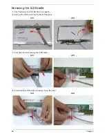
Removing the LCD Bezel
1.
See “Removing the LCD Bezel” on page 92.
2.
Remove the two bezel screw caps and screws.
3.
Starting from the bottom edge of the bezel, pry the bezel upwards and away from the panel. Work along the
side toward the top of the bezel, prying the covers apart. Continue along the top edge and down the other side
to remove the bezel.
NOTE:
If necessary, use a pry to lift up the outside edges of the bezel.
Step
Size
Quantity
Screw Type
LCD Bezel
M2.5*6
2
Summary of Contents for ENTK83 Series
Page 6: ...VI...
Page 10: ...X Table of Contents...
Page 38: ...28 Chapter 1...
Page 55: ...Chapter 2 45...
Page 56: ...46 Chapter 2...
Page 71: ...Chapter 3 61 4 Detach the WLAN module from the WLAN socket...
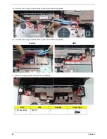
Page 88: ...78 Chapter 3 5 Lift the Bluetooth cable from the cable guides Discrete UMA...
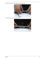
Page 99: ...Chapter 3 89 8 Remove the LCD assembly from the lower cover...
Page 110: ...100 Chapter 3 5 Lift the microphone set clear of the panel...
Page 121: ...Chapter 3 111 4 Replace the adhesive tape securing the inverter board cable to the LCD cover...
Page 127: ...Chapter 3 117 7 Replace the adhesive tape to secure the antennas to the lower cover...
Page 138: ...128 Chapter 3 4 Connect the USB cable to the mainboard and lock the connector...
Page 144: ...134 Chapter 3 Replacing the Upper Cover 1 Place the upper cover on the lower cover as shown...
Page 146: ...136 Chapter 3 4 Connect the speaker cable B 5 Connect and lock the touchpad FFC C...
Page 150: ...140 Chapter 3 4 Slide the HDD module in the direction of the arrow to connect the interface...
Page 160: ...150 Chapter 3...
Page 188: ...178 Chapter 5...
Page 219: ...Chapter 6 209...
Page 228: ...Appendix A 200...
Page 236: ...208 Appendix C...
Page 240: ...212...


