Chapter 6
189
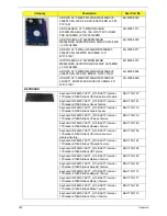
Keyboard GATEWAY AC7T_G10B AC7T Internal
17 Standard 104KS Black Hungarian Texture
KB.I170G.182
Keyboard GATEWAY AC7T_G10B AC7T Internal
17 Standard 104KS Black Norwegian Texture
KB.I170G.187
Keyboard GATEWAY AC7T_G10B AC7T Internal
17 Standard 104KS Black Portuguese Texture
KB.I170G.188
Keyboard GATEWAY AC7T_G10B AC7T Internal
17 Standard 104KS Black Spanish Texture
KB.I170G.191
Keyboard GATEWAY AC7T_G10B AC7T Internal
17 Standard 104KS Black US w/ Canadian French
Texture
KB.I170G.199
Keyboard GATEWAY AC7T_G10B AC7T Internal
17 Standard 104KS Black Turkish Texture
KB.I170G.195
Keyboard GATEWAY AC7T_G10B AC7T Internal
17 Standard 104KS Black Sweden Texture
KB.I170G.192
Keyboard GATEWAY AC7T_G10B AC7T Internal
17 Standard 104KS Black FR/Arabic Texture
KB.I170G.178
Keyboard GATEWAY AC7T_G10B AC7T Internal
17 Standard 104KS Black Nordic Texture
KB.I170G.186
Keyboard GATEWAY AC7T_G10B AC7T Internal
17 Standard 104KS Black SLO/CRO Texture
KB.I170G.190
Keyboard GATEWAY AC7T_G10B AC7T Internal
17 Standard 104KS Black CZ/SK Texture
KB.I170G.175
Keyboard GATEWAY AC7T_G10B AC7T Internal
17 Standard 104KS Black Brazilian Portuguese
Texture
KB.I170G.174
Keyboard GATEWAY AC7T_G10B AC7T Internal
17 Standard 107KS Black Japanese Texture
KB.I170G.184
BD COMBO DRIVE
ODD BD COMBO MODULE
6M.BQ502.005
ODD HLDS BD COMBO 12.7MM TRAY DL 4X
CT21N LF W/O BEZEL 1.00 SATA (HF +
WINDOWS 7)
KO.0040D.004
ODD SONY BD COMBO 12.7MM TRAY DL 4X BC-
5500H LF W/O BEZEL SATA (HF + WINDOWS 7)
KO.0040E.003
ODD SONY BD COMBO 12.7MM TRAY DL 4X BC-
5540H LF+HF W/O BEZEL SATA (HF + WINDOWS
7)
KO.0040E.005
ODD BRACKET
33.R4F02.002
ODD BEZEL-BD
42.R4F02.003
Category
Description
Acer Part No.
Summary of Contents for ENTK83 Series
Page 6: ...VI...
Page 10: ...X Table of Contents...
Page 38: ...28 Chapter 1...
Page 55: ...Chapter 2 45...
Page 56: ...46 Chapter 2...
Page 71: ...Chapter 3 61 4 Detach the WLAN module from the WLAN socket...
Page 88: ...78 Chapter 3 5 Lift the Bluetooth cable from the cable guides Discrete UMA...
Page 99: ...Chapter 3 89 8 Remove the LCD assembly from the lower cover...
Page 110: ...100 Chapter 3 5 Lift the microphone set clear of the panel...
Page 121: ...Chapter 3 111 4 Replace the adhesive tape securing the inverter board cable to the LCD cover...
Page 127: ...Chapter 3 117 7 Replace the adhesive tape to secure the antennas to the lower cover...
Page 138: ...128 Chapter 3 4 Connect the USB cable to the mainboard and lock the connector...
Page 144: ...134 Chapter 3 Replacing the Upper Cover 1 Place the upper cover on the lower cover as shown...
Page 146: ...136 Chapter 3 4 Connect the speaker cable B 5 Connect and lock the touchpad FFC C...
Page 150: ...140 Chapter 3 4 Slide the HDD module in the direction of the arrow to connect the interface...
Page 160: ...150 Chapter 3...
Page 188: ...178 Chapter 5...
Page 219: ...Chapter 6 209...
Page 228: ...Appendix A 200...
Page 236: ...208 Appendix C...
Page 240: ...212...


