Chapter 6
187
CPU/PROCESSOR
CPU AMD ATHLONII P320 2.1G 1M 25W DUAL-
CORE
KC.AP002.320
CPU AMD ATHLONII P340 PGA 2.2G 1M 25W
KC.AP002.340
CPU AMD - V140 PGA 2.3G 512K 25W
KC.V0002.140
CPU AMD PHENOMII N830 2.1G 35W 1.5M L2,
TRIPLE-CORE
KC.PN002.830
CPU AMD PHENOMII N850 PGA 2.2G 1.5M 35W
KC.PN002.850
CPU AMD PHENOMII N930 2.0G 2M 35W QUAD-
CORE
KC.PN002.930
CPU AMD PHENOMII N950 PGA 2.1G 2M 35W
KC.PN002.950
CPU AMD TURIONII P540 PGA 2.4G 2M 25W
KC.TP002.540
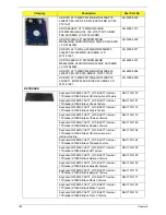
HDD/HARD DISK DRIVE
HDD SEAGATE 2.5" 5400RPM 160GB
ST9160314AS,9HH13C-189, SEAGATE(NEW
PCB) SATA 8MB LF F/W:0001SDM1
KH.16001.045
HDD TOSHIBA 2.5" 5400RPM 160GB
MK1665GSX, CAPRICORN BS, 320G/P SATA
8MB LF F/W:GJ002J
KH.16004.008
HDD HGST 2.5" 5400RPM 160GB
HTS545016B9A300 PANTHER B SATA LF F/
W:C60F DISK IMBALANCE CRITERIA = 0.014G-
CM
KH.16007.026
HDD SEAGATE 2.5" 5400RPM 250GB
ST9250315AS, 9HH132-189, WYATT WITH NEW
PCB SATA 8MB LF F/W:0001SDM1
KH.25001.019
HDD TOSHIBA 2.5" 5400RPM 250GB
MK2565GSX, CAPRICORN BS, 320G/P SATA
8MB LF F/W:GJ002J
KH.25004.005
HDD HGST 2.5" 5400RPM 250GB
HTS545025B9A300 PANTHER B SATA LF F/
W:C60F DISK IMBALANCE CRITERIA = 0.014G-
CM
KH.25007.016
HDD WD 2.5" 5400RPM 250GB WD2500BEVT-
22A23T0, WD, ML320S SATA 8MB LF F/
W:01.01A01.
KH.25008.025
HDD SEAGATE 2.5" 5400RPM 320GB
ST9320310AS,9RN132-188, CAMERON 320G/P
SATA 8MB LF F/W:0001SDM1
KH.32001.019
HDD TOSHIBA 2.5" 5400RPM 320GB
CAPRICORN BS ,MK3265GSX SATA 8MB LF F/
W:GJ002J
KH.32004.004
HDD HGST 2.5" 5400RPM 320GB
HTS545032B9A300 PANTHER B SATA LF F/
W:C60F DISK IMBALANCE CRITERIA = 0.014G-
CM
KH.32007.008
HDD WD 2.5" 5400RPM 320GB WD3200BEVT-
22A23T0,ML320S,WD SATA 8MB LF F/
W:01.01A01
KH.32008.019
Category
Description
Acer Part No.
Summary of Contents for ENTK83 Series
Page 6: ...VI...
Page 10: ...X Table of Contents...
Page 38: ...28 Chapter 1...
Page 55: ...Chapter 2 45...
Page 56: ...46 Chapter 2...
Page 71: ...Chapter 3 61 4 Detach the WLAN module from the WLAN socket...
Page 88: ...78 Chapter 3 5 Lift the Bluetooth cable from the cable guides Discrete UMA...
Page 99: ...Chapter 3 89 8 Remove the LCD assembly from the lower cover...
Page 110: ...100 Chapter 3 5 Lift the microphone set clear of the panel...
Page 121: ...Chapter 3 111 4 Replace the adhesive tape securing the inverter board cable to the LCD cover...
Page 127: ...Chapter 3 117 7 Replace the adhesive tape to secure the antennas to the lower cover...
Page 138: ...128 Chapter 3 4 Connect the USB cable to the mainboard and lock the connector...
Page 144: ...134 Chapter 3 Replacing the Upper Cover 1 Place the upper cover on the lower cover as shown...
Page 146: ...136 Chapter 3 4 Connect the speaker cable B 5 Connect and lock the touchpad FFC C...
Page 150: ...140 Chapter 3 4 Slide the HDD module in the direction of the arrow to connect the interface...
Page 160: ...150 Chapter 3...
Page 188: ...178 Chapter 5...
Page 219: ...Chapter 6 209...
Page 228: ...Appendix A 200...
Page 236: ...208 Appendix C...
Page 240: ...212...


