www.packardbell.com
87
9
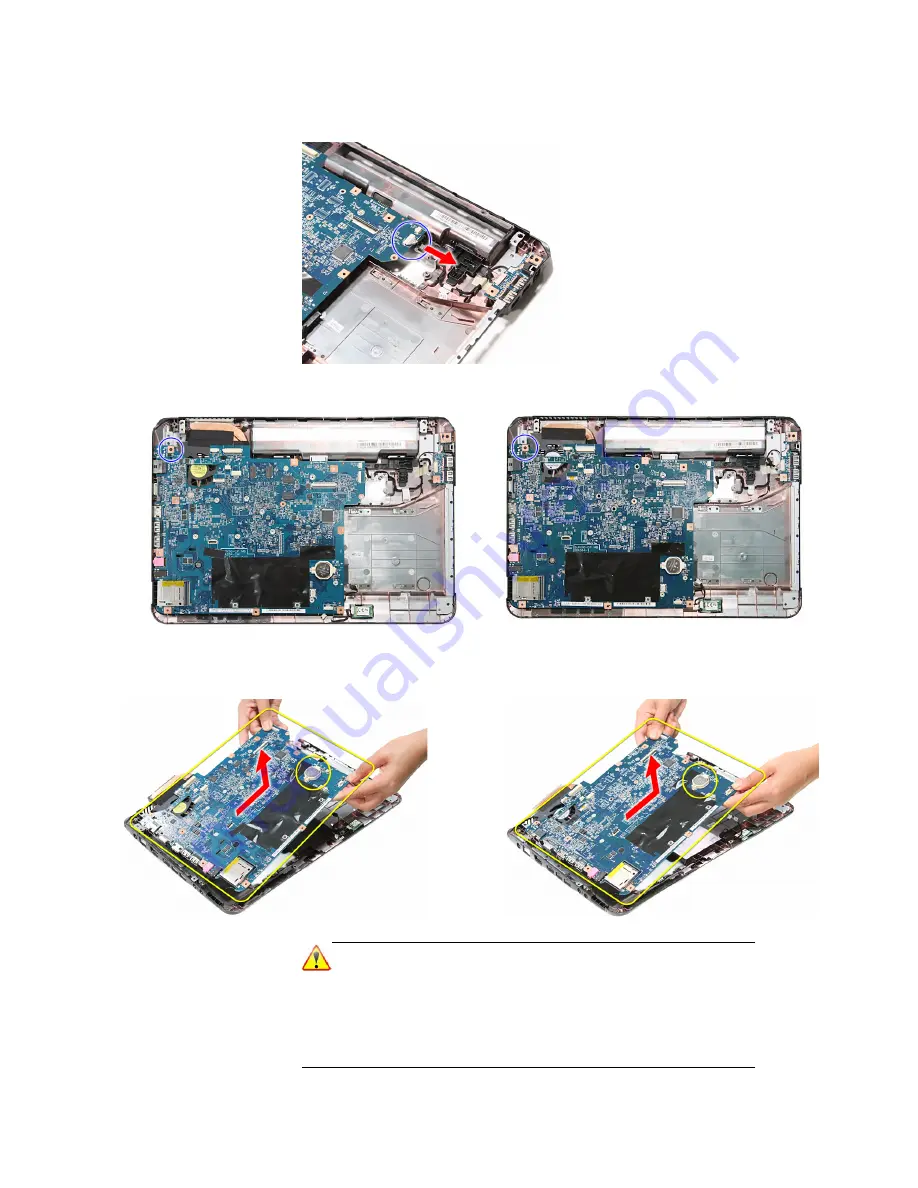
Disconnect the USB board cable from its system board connector.
10
Remove the system board screw.
11
Carefully remove the system board from the base enclosure.
Note
A circuit board that is >10 cm
2
has been highlighted with a yellow
rectangle as shown in the previous image. Follow the local
regulations for disposing this type of circuit board.
The RTC battery has been highlighted with a yellow circle in the
previous image. Detach the RTC battery and follow the local
regulations for disposing it.
Discrete model
UMA model
Discrete model
UMA model
Summary of Contents for ENTJ75
Page 1: ...ENTJ75 ENTJ76 ENTJ77 ENTJ78 SERVICEGUIDE ...
Page 6: ...Contents iv ...
Page 12: ...CHAPTER 1 System specifications 6 System block diagram ...
Page 48: ...CHAPTER 2 System utilities 42 ...
Page 140: ...CHAPTER 4 Troubleshooting 134 ...
Page 141: ...CHAPTER5 135 Connector locations System board layout ...
Page 145: ...CHAPTER6 139 FRU Field Replaceable Unit list Introduction Exploded diagram FRU list ...
Page 152: ...CHAPTER 6 FRU Field Replaceable Unit list 146 ...
Page 153: ...APPENDIXA 147 Test compatible components Introduction Microsoft Windows 7 Compatibility Test ...
Page 156: ...APPENDIX A Test compatible components 150 ...
Page 157: ...APPENDIXB 151 Online support information ...
Page 163: ......
Page 164: ...MAN NV5x SVC GDE R1 04 09 ...


