www.packardbell.com
77
5
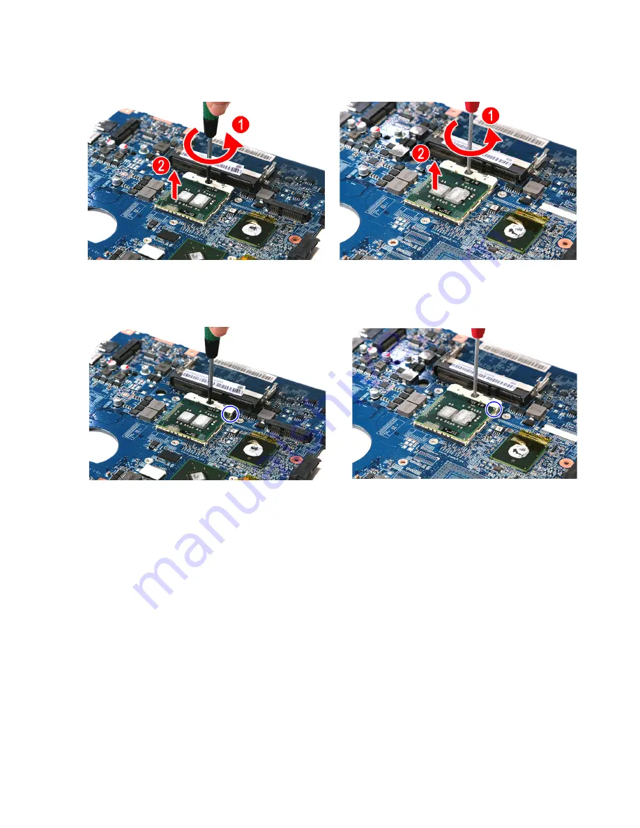
Remove the old processor from the system board
(2)
.
6
Align pin 1 of the new processor (indicated by the gold arrow on the corner
of the processor) with the beveled corner of the processor socket.
The processor will easily fit into the socket if you oriented it properly.
7
Use a flat-blade screwdriver to turn the lock screw 180° clockwise to secure
the processor in place.
8
Apply just enough thermal grease to evenly coat the surface of the processor
die.
9
Reinstall the cooling assembly by performing steps
8
–
11
of the
“Replacing
the cooling assembly”
procedure on
page 73
.
10
Reinstall the system board by performing steps
20
and
21
of the
“Replacing
the system board”
procedure on
page 69
.
11
Reconnect the USB board and Bluetooth module cables to their system
board connectors.
12
Reinstall the Bluetooth module by performing step
11
of the
“Replacing the
Bluetooth module”
procedure on
page 67
.
13
Reinstall the USB board by performing steps
10
–
11
of the
“Replacing the
USB board”
procedure on
page 65
.
14
Reinstall the LCD panel assembly by following the steps
16
–
26
of the
“Replacing the LCD panel assembly”
procedure on
page 61
.
UMA model
Discrete model
UMA model
Discrete model
Summary of Contents for EasyNote NM85
Page 1: ...EasyNote NM85 NM86 NM87 NM89 NM98 SERVICEGUIDE ...
Page 6: ...Contents iv ...
Page 12: ...CHAPTER 1 System specifications 6 System block diagram ...
Page 38: ...CHAPTER 2 System utilities 32 ...
Page 100: ...CHAPTER 3 Replacing notebook components 94 ...
Page 120: ...CHAPTER 4 Troubleshooting 114 ...
Page 121: ...CHAPTER5 115 Connector locations System board layout ...
Page 125: ...CHAPTER6 119 FRU Field Replaceable Unit list Introduction Exploded diagram FRU list ...
Page 133: ...APPENDIXA 127 Test compatible components Introduction Microsoft Windows 7 Compatibility Test ...
Page 137: ...APPENDIXB 131 Online support information ...
Page 141: ......
Page 142: ...MAN NV5x SVC GDE R1 04 09 ...


