19
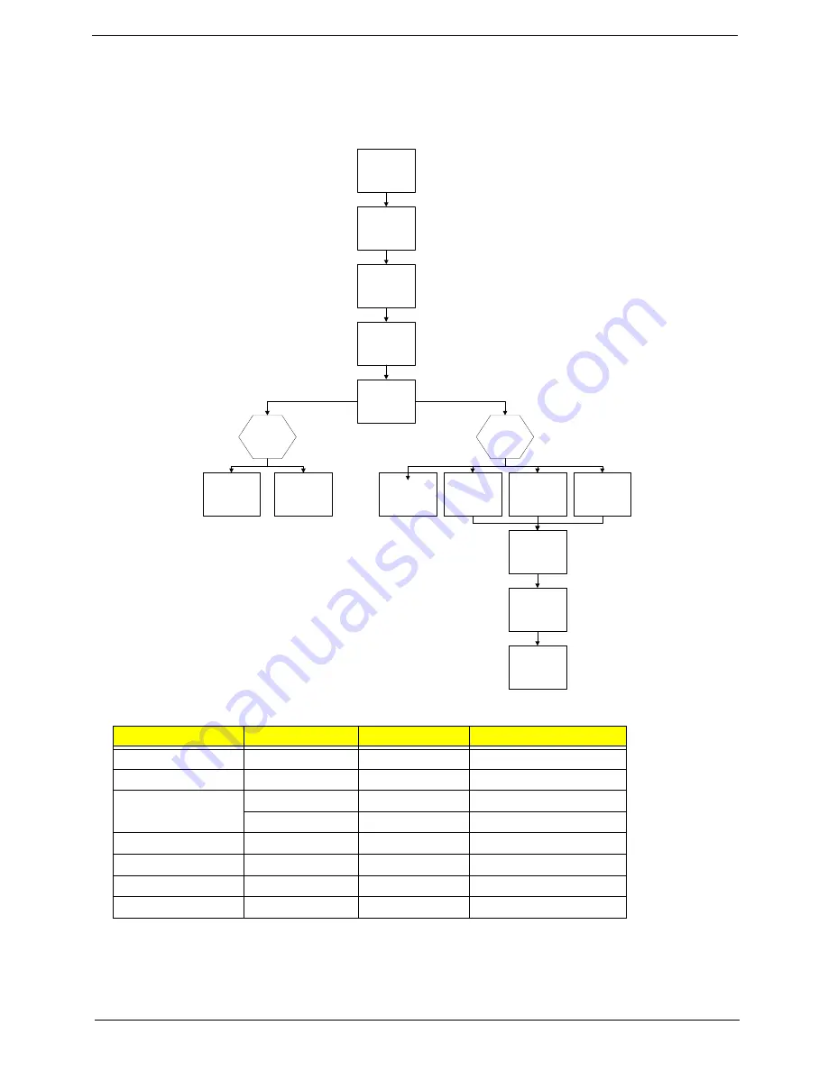
Main Unit Disassembly Process
Main Unit Disassembly Flowchart
Screw List
Step
Screw
Quantity
Part No.
Switch Cover
M2.5*6.0
3
86.W0907.002
LCD Module
M2.5*6.0
4
86.W0907.002
Upper Cover
M2.5*6.0
8
86.W0907.002
M2.5*6.0
10
86.W0907.002
Speaker Modules
M2*3
4
86.A08V7.005
Modem Board
M2*3
2
86.A08V7.005
USB Board
M2*3
1
86.A08V7.005
Mainboard
M2.5*6.0
1
86.W0907.002
Remove
Mainboard
Remove
USB Board
Remove
Switch Cover
Remove
Keyboard
Remove
Upper Cover
Remove
LCD Module
Remove External
Modules before
proceeding
Remove
TouchPad FFC
Upper
Cover
Lower
Cover
Remove
Speaker Module
Remove
Modem Module
Remove
CPU
Remove
RTC Battery
Remove
Thermal Module
Remove
Bluetooth
Summary of Contents for EasyNote NJ Series
Page 6: ...6 ...
Page 30: ...30 7 Lift the Upper Cover clear of the computer as shown ...
Page 33: ...33 7 Lift the Speaker Modules clear of the Upper Cover ...
Page 38: ...38 5 Disconnect the Bluetooth cable from the module ...
Page 40: ...40 4 Turn the USB Board over and disconnect the USB cable from the board ...
Page 51: ...51 4 Remove the LCD Panel rear edge first Place it on a clean surface ...


