background image

-


-


-


-


-


-


-


-


-


-


-


-


-


-


-


-


-


-


-


-


-


-


-


-


-


-


-


-


-


-


-


-


-


-


-


-


-


-


-


-


-


-


-


-


-


-


-


-


-


-

  ▲           

I

NSTRUCTION 

M

ANUAL


MEGA

-

T400S


Abrasive Cutter


3601 E. 34th St. Tucson, AZ  85713  USA  Tel. +1

-

520

-

882

-

6598  Fax +1

-

520

-

882

-

6599  email: [email protected]    Web: https://www.metallographic.com


Please read this instruction manual carefully and follow all installation, operating and safety guidelines.


7.0  Metallographic Cutting Basics


21


Philosophy:


1.


Cutting is the most important metallographic sample preparation step


2.


Minimize damage during sectioning


3.


Less sectioning damage = reduced number of grinding and polishing steps


Note: I

n some cases cutting damage cannot be removed by subsequent polishing operations 

(especially for brittle samples)


Time Well Spent:


1.


Spend more time on sectioning in order to decrease overall sample preparation time


2.


Protect integrity of the specimen with proper sectioning


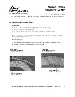
Wheel feed


-

High speed (3500 rpm)


-

High load (10 amps)


Table feed


-

Low speed (1500 rpm)


-

Low load (3 amps)


Finer finish with 

minimal cutting burr


Coarse finish with 

large cutting burr


Summary of Contents for MEGA-T400S

Page 1: ...truction manual carefully and follow all installation operating and safety guidelines Equipment Type 400 mm 16 inch Manual Abrasive Cut off Machine Model MEGA T400S Electrical Requirements 480 Volts 3 phase Frequency 50 60 Hz Motor Horsepower Variable speed Servo Motor 12 KW 16 hp 480V 3 phase Manual Revision Date March 16 2023 This instruction manual is provided with each piece of delivered equip...

Page 2: ...ue and not a warranty issue PACE TECHNOLOGIES MAKES NO EXPRESS WARRANTIES OTHER THAN THOSE WHICH ARE SPECIFICALLY DESCRIBED HEREIN Any description of the goods sold hereunder including any reference to Buyer s specifications and any description in catalogs circulars and other written material published by PACE Technologies is the sole purpose of identifying such goods and shall not create an expre...

Page 3: ...er or any other agreement between Buyer and Seller Buyer s rights under the warranty shall be suspended during any period of such default and the original warranty period will not be extended beyond its original expiration date despite such suspension of warranty rights 7 MISCELLANEOUS PROVISIONS This agreement has been made in and shall be governed by the laws of the State of Arizona All disputes...

Page 4: ...r 3601 E 34th St Tucson AZ 85713 USA Tel 1 520 882 6598 Fax 1 520 882 6599 email pace metallographic com Web https www metallographic com Please read this instruction manual carefully and follow all installation operating and safety guidelines iv ...

Page 5: ... com Please read this instruction manual carefully and follow all installation operating and safety guidelines Contents PAGE Nameplate i Warranty ii 1 0 Product Description 1 2 0 Shipping Unpacking and Installation 6 3 0 Safety Guidelines 9 4 0 Start Up and Operation 12 5 0 Maintenance 18 6 0 Trouble Shooting 19 7 0 Cutting Basics 21 8 0 Electrical and Mechanical Drawings 24 v ...

Page 6: ... durable with its cast aluminum alloy and stainless steel construction Featuring a corrosion free T slot table the MEGA T400S is a very versatile wheel table feed floor model metallographic cutter 1 Control Screen Manual wheel feed Cutting chamber Table wheel feed Blade Height Locking Screw Safety Lock out Emergency Stop Control knobs Powerful motor The MEGA T400S is equipped with a powerful belt ...

Page 7: ...ines 2 T slot table LED light inside Removable side port for longer feed through samples Pass through side panels for long sample access Safety lock out for protecting user against moving blade When current setting is exceeded a red flashing light appears inside 1 When closing the hood press down the hood to ensure that the safety switch is engaged 2 After the cut has finished if the hood lock doe...

Page 8: ...2 6599 email pace metallographic com Web https www metallographic com Please read this instruction manual carefully and follow all installation operating and safety guidelines Easy to use vises 3 Coolant applied through the shroud directly to the blade Flexible coolant hose for application to cutting area optional ...

Page 9: ...s max 20 amps Electronic motor brake Stops in 3 5 seconds Cut off wheels 16 inch mm 400 mm diameter Wheel arbor 32 mm 1 25 inch diameter Maximum sample diameter 6 inch 150 mm diameter 3 x 6 inches 75 x 150 mm HxD Wheel feed Manual Table feed Manual Vertical movement 5 inch 125 mm Weight Approx 880 lbs 400 kg Dimensions WxDxH Hood Closed 48 x 51 x 63 inch 1220 cm x 1300 cm x 1600 cm Hood Open 48 x ...

Page 10: ...om Web https www metallographic com Please read this instruction manual carefully and follow all installation operating and safety guidelines 1 3 Mechanical Schematic Note Installation of the MEGA T400S should be on a flat sturdy surface with easy access to electrical connections 5 MEGA T400S hood open dimensions MEGA T400S hood closed dimensions ...

Page 11: ...0 pounds 2 2 Shipping When moving crate lift from bottom To move MEGA T400S use support bars provided with the machine The MEGA T400S contains sensitive electronic and mechanical components Do not drop CAUTION Heavy equipment Take care to avoid bodily injury 6 Installation continued on next page Casters set for moving cutter Casters set for stationary support Machine includes support bars to lift ...

Page 12: ...e electrical connections to a 3 phase power line The motor driver max amp draw is 20 amps However the operating power is set to 15 amps Electrical Connections The standard saw is designed to operate at 208 220V 3 phase 120V 120V 120V ground optional 380V Verify voltage on nameplate Connect pump connector supply line from cutter to the pump and insert the drain hose into the basket filter Verify th...

Page 13: ...n Pump Tank drain valve External coolant supply Attach 3 4 inch tube between pump and cutter Drain 1 5 inch 38 mm tube Electrical connections Connect electrical power cable to source NOTE Inspect the operating voltage on the name plate Electrical connection for external coolant supply Power for recirculation system comes from the MEGA T400S Recommended Coolant To help minimize corrosion apply a co...

Page 14: ...oper operator training is required for the safe operation of the MEGA T400S Any unauthorized mechanical and electrical change as well as improper operation voids all warranty claims All service issues need to be reported to the manufacturer supplier Before operating cutting chamber hood must be closed After cutting the safety latch will not open for approximately 2 8 seconds after pressing the eme...

Page 15: ...llation operating and safety guidelines Recirculation Tank The MEGA T400S is equipped with a coarse filter to remove large particulate and broken blades NOTE Dispose of the old coolant in ordnance with federal state and local regulations Electrical connection Pressure line After use water off the cutting chamber to prevent debris and corrosion build up Water valve Rinse line 10 Drain line Coarse s...

Page 16: ... Response Machine powers down and motor stops in 5 10 seconds Malfunction Machine does not lose power Corrective measure If system does not power down disconnect power supply cord and call service technician Magnetic safety lock out switch Test Activate the main switch and close the hood turn cut off wheel ON then OFF Try to open the hood Proper Response The hood does not open for approxi mately 3...

Page 17: ...h screen control Information Screen Note When first powering up the MEGA T400S the initialization time for the saw is approximately 15 seconds The servo motor is also designed to increase speed slowly and typical takes 4 5 seconds to reach full speed Cutting wheel ON Starts the cutting wheel Cutting wheel OFF Stops the cutting wheel inductive brake engages to slowing wheel The hood will not open u...

Page 18: ...installation operating and safety guidelines Start up screen Press control panel knob to progress to information screen START UP SCREEN INFORMATION READY SCREEN OPERATING SCREEN Information screen set speed and force amps by selecting parameter on the touch screen and adjusting the parameter in the sub screen Repeat for other parameter Set Speed Actual Operating Speed Cutting force amps Setting Pe...

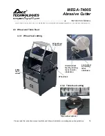
Page 19: ...ww metallographic com Please read this instruction manual carefully and follow all installation operating and safety guidelines 4 3 Wheel and Table Feed Wheel feed chop cut Unlock wheel feed by turning lever counter clockwise 4 3 1 Wheel feed cutting 4 3 2 Table feed cutting Open wheel spinner Table feed wheel Lock wheel by turning lever clockwise 14 Wheel lock ...

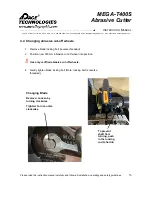
Page 20: ...allation operating and safety guidelines 1 Remove blade locking bolt reverse threaded 2 Position new 350 mm abrasive cut off wheel into position 3 Use only certified abrasive cut off wheels 4 Gently tighten blade locking bolt Note locking bolt is reverse threaded 4 4 Changing abrasive cut off wheels 15 Changing Blade Remove Loosen by turning clockwise Tighten Turn counter clockwise To prevent shaf...

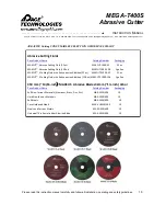
Page 21: ...Fluid 128 oz MAXCUT 1000 128 1 gallon MAXCUT 2 Cutting Fluid with Anticorrosion Additive 32 oz MAXCUT2 1000 32 32 oz MAXCUT 2 Cutting Fluid with Anticorrosion Additive 128 oz MAXCUT2 1000 128 1 gallon 350 mm 14 16 inch MAXCUT Abrasive Blades 32mm 1 inch Arbor Pace Product Name Catalog Number Packaging Soft Non ferrous Materials Aluminum Brass Zinc Etc MAX E350 400 10 Hard Non ferrous Materials MAX...

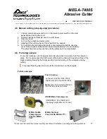
Page 22: ...6 Fixturing sample 17 Fast clamping Left lever Cat No QCL 1000 Right lever Cat No QCR 1000 Note vises have a slot in them so that the face does not rotate UNIVERSAL Clamping vise UNIVERSAL Cat No MG 01 Clamping height 45mm 1 8 inch MEGA Saddle Clamping vise Cat No MEGA 702 MEGA Fastener Vise Cat No MEGA 711 17 4 5 Manual cutting step by step procedure 1 Connect electrical power and turn on the mas...

Page 23: ...he table and vises after use 4 When the cutter is not in use OPEN the HOOD to prevent humidity and corrosion build up inside the cutting chamber 5 If cutter will not be used for an extended period coat the table and vises with a water displacement oil such as WD 40 6 Use only recommended abrasive blades to minimize overheating of the bearings and motor Do not exceed the recommended amp rating of t...

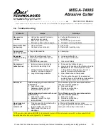
Page 24: ...rage oxidation a Rinse and dry table and vises b Use an anti corrosion cutting fluid such as the MAXCUT 2 It is recommended that the cutting fluid be changed every 50 cuts or weekly for maximum effectiveness c Open hood when not being used d If cutter will not be used for an extended period of time coat the table and vises with a water displacement oil such as WD 40 ERROR 01 Sudden stopping of mot...

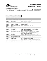
Page 25: ...te parameters ERR 05 GF Bus under or over volt age Check the voltage and parameters ERR 06 Communication anomaly Check the wire connection ERR 07 Locate failed Check the encoder signal Or the current feedback wrong Reposition and try again ERR 08 Lost step when running Normally the reverse angle is 2 degrees and the re verse angle is 20 degrees when positioning will be wrong Reposition and try aga...

Page 26: ...c sample preparation step 2 Minimize damage during sectioning 3 Less sectioning damage reduced number of grinding and polishing steps Note In some cases cutting damage cannot be removed by subsequent polishing operations especially for brittle samples Time Well Spent 1 Spend more time on sectioning in order to decrease overall sample preparation time 2 Protect integrity of the specimen with proper...

Page 27: ...Silicon Carbide Alumina Abrasive Bond Resin Rubber Cutting Force Control by motor current Cutter Speed Low 1500 2000 rpm Medium 2000 2500 rpm High 2500 3500 rpm Coolant Water based Oil Emulsion based Five variables for successful sectioning Metallographic Abrasive Blades Resin Bonded Blades Breakdown easily Less smell and burning More versatile Alumina abrasives Rubber Bonded Blades Longer life Pr...

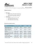
Page 28: ...d 3 5 amps Most metals medium load 6 10 amps Machine Parameters Material Abrasive Bond Blade Cutting Speed Cutting Force Soft non ferrous metals aluminum brass zinc etc Alumina resin MAX E 1500 rpm 3 5 amps Hard non ferrous metals titanium zirconium etc SiC rubber MAX C 2300 rpm 5 10 amps Soft steels Alumina resin MAX E 1500 rpm 5 10 amps Hard and case hardened steels Alumina resin MAX VHS 1900 rp...

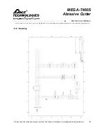
Page 29: ... E 34th St Tucson AZ 85713 USA Tel 1 520 882 6598 Fax 1 520 882 6599 email pace metallographic com Web https www metallographic com Please read this instruction manual carefully and follow all installation operating and safety guidelines 24 8 0 Drawing ...

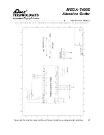
Page 30: ...r 3601 E 34th St Tucson AZ 85713 USA Tel 1 520 882 6598 Fax 1 520 882 6599 email pace metallographic com Web https www metallographic com Please read this instruction manual carefully and follow all installation operating and safety guidelines 25 ...

Reviews: