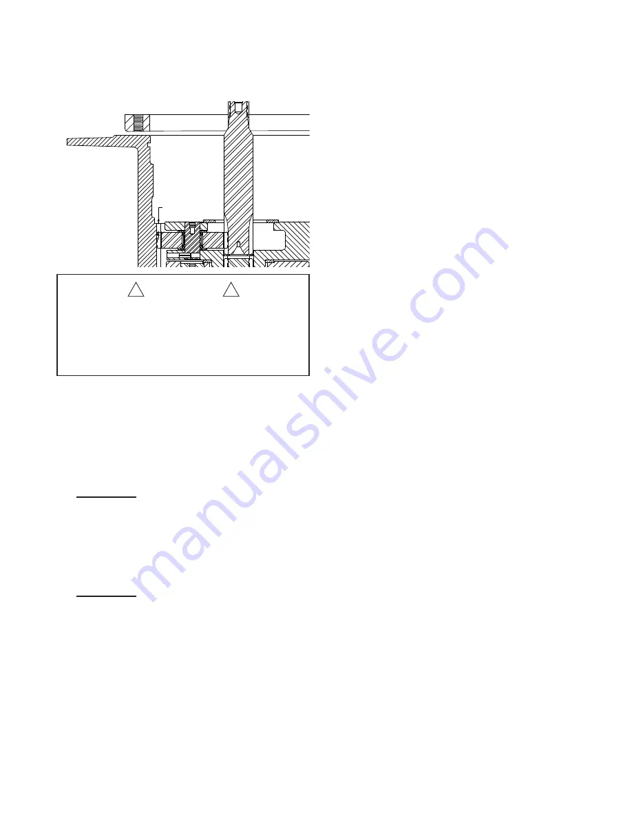
DO NOT
proceed with assembly if the primary
planet gears are not engaged with the ring as
shown in the drawing above. Check the location
of all thrust washers to be sure they are properly
positioned.
10. Install a new bearing in the drum closure if required.
BG8A ONLY:
Apply a nonhardening sealant on the
outside surface of a new oil seal. Install with spring
side of the seal toward the bearing, using a flat
plate to avoid distortion. Install a new O-ring in the
drum.
11. Lubricate the drum opening with petroleum jelly or
gear oil and install the drum closure into the drum.
BG8B ONLY:
Apply a nonhardening sealant on the
outside surface of a new oil seal. Install with spring
side of the seal toward the drum closure, using a
flat plate to avoid distortion.
12. Lubricate the pilot, oil seal and bearing surfaces
of the brake cylinder and carefully install brake
cylinder into base and drum. Be careful that the
brake cylinder pilot fits into the thrust washer on the
primary planet carrier. When correctly installed, the
brake cylinder will fit against the winch base.
13. Install and tighten brake cylinder capscrews and
lockwashers. Tighten to recommended torque.
14. Install the brake clutch assembly.
When installed correctly, the cam should turn freely
in the opposite direction the drum turns to pull wire
rope in. An easy way to check the rotation is to hold
the outer race in one hand, and rotate the cam.
15. If the brake discs are misaligned, preventing the
installation of the clutch, apply 750-1000 PSI
(5170-6900 kPa) to the brake release port with a
hand pump. The brake discs will move freely with
the brake released, permitting alignment of the
discs, brake clutch and input sun gear.
16. Install a new O-ring on the motor pilot then lubri-
cate with petroleum jelly or gear oil. Engage the
motor shaft with the inside race of the brake clutch
and lower motor into place. Install and tighten cap-
screws to recommended torque.
17. Install the hoses and fittings to the brake cylinder
release port, manifold and brake valve.
18. After the winch assembly is complete, check all
capscrews and fittings to make certain they have
been tightened correctly.
Refill the winch with the recommended oil listed
under “Preventive Maintenance,” and install the oil
level plug.
Operate the winch slowly in both directions and
check for oil leaks and/or unusual sounds from the
winch. The winch should operate smoothly in both
directions. Refer to “WIRE AND BRAIDED ROPE
INSTALLATION” and properly install rope onto the
winch drum.
Before returning the winch to full service, a light
load should be lifted and held a few feet off the
ground to be sure the static brake is functioning
properly. The winch should also be able to slowly
lower the load in a smooth and controlled manner.
If the winch does not perform either of these func-
tions, refer to “TROUBLESHOOTING” for additional
information.
26
3/8 inch
9.5 mm)
When all components are correctly installed, the pri-
mary planet gears will be approximately 3/8 inch (9.5
mm) below the ring gear, as shown above. Binding
and damage to the gear train may result if one or
more of the thrust washers is incorrectly installed.
CAUTION
!
!


