Instruction Manual
Updated11/2013
13
| 24
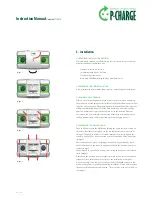
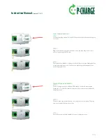
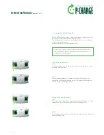
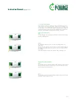
You can now lift off the housing. A strain relief device to each side connects
it with the base plate of the electrical components. The strain relief devices
should not be removed. Lift the base plate together with the housing cover
away from the Wallbox rear mounting panel. The Wallbox is now lying in 2
parts before you: the plastic Wallbox rear mounting panel and the base plate
with the housing.
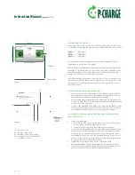
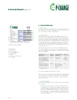
5.5 preparing for the on-Wall connection
Insofar as the electric supply line and/or the data line/s are surface mounted
(on-wall) and routed into the Wallbox, the housing rear panel must make
provision for this. Lines may enter the device at the top side as well as at the
lower side of the two cable entry hoods at the housing rear panel. At each
hood, there are three possible entry points; their middle points are marked
with a hole.
In each case, imperatively ensure that the protection class IP54 (protected
against harmful dust amount / protection against splashing water from any
direction) is safeguarded following mounting and installation of the cable
entry glands, i.e. appropriate cable entries must be used. Cable glands must be
mounted in accordance with the manufacturer's specifi cations (seals, tighten-
ing torque etc.).
Besides, when setting the drill holes please consider that (transverse) forces on
the rear panel should be avoided wherever possible; otherwise the adhesive
bond between the rear panel and the cable entry hood might be damaged.
proceDure for creating cable entry-points
1.
Defi ne the position and number of entry-points
2.
Determine the exact size of the glands to be installed
3.
Place the cable entry hood fl atly onto a horizontal worktop.
Please avoid damage to the surface of the cable entry hood (remove dirt/
dust; apply protective foil if necessary)
4.
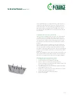
Pre-drill the middle points from the inside using a twist drill (see image)
with a diameter of approx. 3-5 mm
5.
Enlarge the bore diameter from the outside (visible side) to the required
diameter, using a stepless quick-helix drill.
6.
Repeat steps 4-5 for further cable entries/bushings.
7.
Mount the cable glands.


