Page 17
Page 16
900-0125-
12
-
02 Rev A
©2017 OutBack Power Technologies. All Rights Reserved.
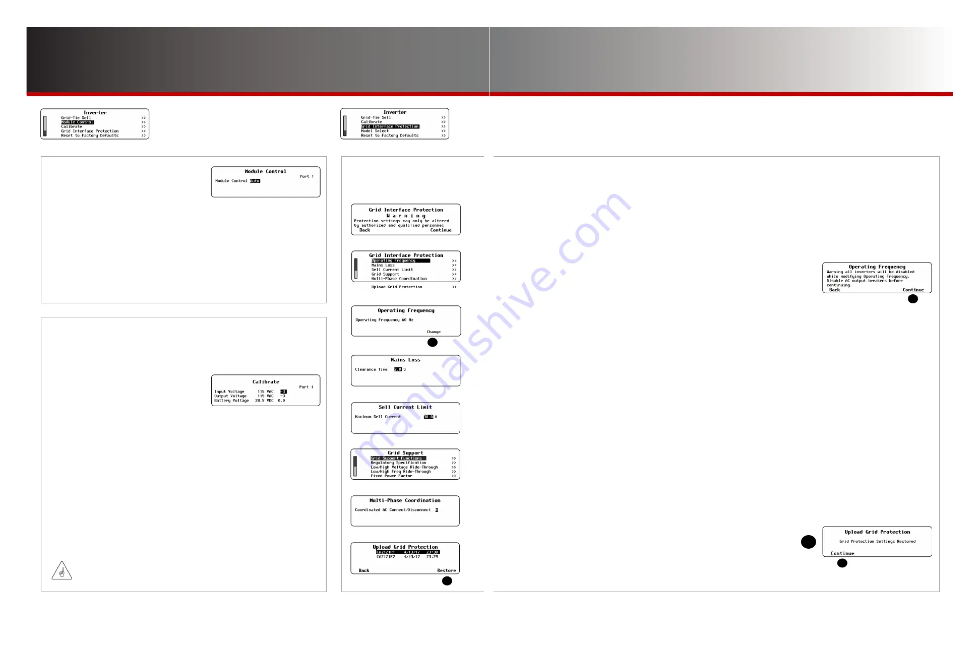
This menu contains sensitive inverter settings. Some settings relate to regional requirements or large system
performance (
Operating Frequency
,
Multi-Phase Coordination
). However, most settings are related
specifically to grid-interactive applications.
All settings are protected as they can noticeably affect inverter operation. The installer password needs
to be initially set before this menu is visible. (
See page 9.) None o
f these settings should be changed
unless required by the utility company or another authority.
Each
Grid Interface Protection
item opens a separate screen with adjustable menu items.
●
Operating Frequency
— This screen has a single item which selects the operating
nominal frequency of the inverter. The options are 60 Hz or 50 Hz. The default setting
depends on the model of inverter. Pressing
Change
(
A
) on this screen leads to a warning
screen (shown to the right) before this setting can be changed with Continue (
B
).
●
Mains Loss
— This screen has a setting for inverter disconnection time (
Clearance Time
)
following the loss of an AC source.
●
Sell Current Limit
— This screen has a single item. It controls the maximum amount of power sold in grid-interactive operation.
The following section is applicable to FXR-class inverters and GS (E) series inverters only.
●
Multi-Phase Coordination
— This screen allows activation of
Coordinated AC Connect/Disconnect
. When this function is active,
the AC source must deliver input (in the appropriate phase) to all inverters. If the master or subphase master inverters do not sense
an acceptable AC source, the entire system will disconnect from the source.
The default state for this function is inactive. If
Coordinated AC Connect/Disconnect
is not active, a stacked inverter system
attempts to remain connected to the AC source as long as the master remains connected, even if other inverters are disconnected.
Disconnected inverters display a
Phase Loss
warning. (Subphase master inverters that are disconnected will return to inverting
mode. Slave inverters will not.)
The following section is applicable to FXR-class inverters and GS (A) series inverters only. The
Grid Interface
Protection
menu displays these items:
●
Grid Support
— This enters an additional series of screens intended for “Grid Support Utility-Interactive Inverters” as defined by
UL1741 SA and other standards. Grid support operation uses inverter grid-interactive capabilities to prevent destabilization
of the grid. The items shown here support operation of grid support functionality under the requirements of utility companies in
various locations around the world. See the next page.
NOTE
: Grid Support functionality is activated by the
Grid Tied
and
GridZero
AC input modes. See page 11. Grid
Support disables certain items such as
Voltage Limit
which are adjustable in other modes.
●
Upload Grid Protection
— These menus can implement any of several .GIP files which can be downloaded from the OutBack
website. The .GIP files pre-load the inverter with the requisite grid support values for various regions. Options for Hawai’i, Australia,
and other locations are available. This function is also useful for restoring the original file if the values were changed in the inverter.
To implement or restore a configuration from an SD card:
1.
A list will be displayed of any .GIP files. Use the control wheel to select the name
of the file to be restored. It is advisable to ensure only one .GIP file is present.
2. Press <
Restore
> to start the process. (See
C
.) Wait for the confirmation
screen
D
to appear.
3. After the screen appears, press <
Continue
> (
E
) to return to the
Main Menu
.
NOTE
: For instructions on installing .GIP files for Grid Support functionality, see the inverter
Installation Manual
.
I-12. Module Control
(Radian-class only)
This item is used to disable either of a Radian-class inverter’s internal
power modules for testing. If one module fails or if troubleshooting is
otherwise needed, the module selection can be performed manually.
The available options are
Auto
,
Left
,
Right
, and
Both
. The inverter can
be directed to use a single, specified module (left or right), or it can turn on
both modules simultaneously.
This procedure should be performed only if directed by OutBack Technical
Support. It should not be performed on inverters that do not have two
power modules.
I-13. Calibrate
This menu allows adjustment of the inverter’s internal voltmeters.
Calibration can improve system performance. Multiple inverters can
achieve voltage targets at the same time.
This image shows the readings taken
by the inverter in Vac and Vdc. To the
right of each value is the calibration
setting which adjusts the reading.
The settable range will vary with inverter model. See the inverter
literature for specific ranges.
●
Input Voltage
— Calibrates the AC voltage measurement made at the inverter’s
AC input (from an incoming AC source).
NOTE
: Radian-class inverters have two
Input Voltage
settings due to the dual inputs.
●
Output Voltage
— Calibrates the AC voltage measurement made at the inverter’s
AC output (from the inverter’s own power, or from an incoming AC source).
●
Battery Voltage
— Calibrates the DC voltage measurement made at the inverter’s
DC terminals.
To calibrate the battery voltage reading:
1.
Place an accurate DC voltmeter at the battery terminals (not the inverter terminals).
2. Operate the inverter at about half power, then adjust the
Battery Voltage
setting
until the inverter’s battery voltage matches the reading on the DC voltmeter.
The AC readings are calibrated similarly at the AC terminals.
Inverter Settings
Grid Interface Protection
I-14. Grid Interface
Protection
(FXR-class and Radian-class with the exception of GS8048)
IMPORTANT:
Calibration does not change the actual output of the inverter, only the reading of
that output.
C
D
A
B
E


