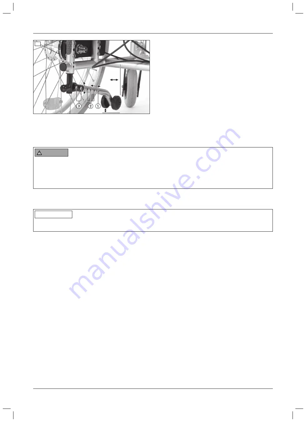
50 mm
26
8 Delivery
8.1 Checking the static stability before putting into service
WARNING
Failing to secure the user while checking the tipping behaviour
User tipping over, falling due to lack of safety measures
►
During the check, have the product secured by at least two attendants on both sides of the tipping direction
(front/rear).
►
Secure the user with positioning belts during the check.
After installing the seating solution, the tipping behaviour of the complete product with the user has to be checked
on a
10°
uphill/downhill grade. The tipping behaviour can vary depending on the composition of the complete
product and the user’s individual situation.
INFORMATION
After checking the tipping behaviour, it is essential to ensure that the complete product with the user stands
stable on a
10°
uphill/downhill grade.
Preparation
1) Prepare a platform with a
10°
grade.
2) Position the user in the seat on the seating shell mobility base and secure them with the positioning belts.
a) Checking the static stability on an uphill grade
1) Assume the least favourable position for driving uphill: foot support assembly angled, seat tilted 30° to the rear,
back support angle 120° (see fig. 27).
2) Push the complete product forward onto the platform.
3) Position the wheels in the direction of travel.
4) Activate the wheel lock.
5) Check the tipping behaviour.
INFORMATION: If the complete product tips backward, static stability can be achieved by readjusting
the following options:
• Anti-tipper (see Page 23)
• Seating centre of gravity (see Page 13)
• Wheelbase (for 22"/24" drive wheels, see Page 19)
→
Check the tipping behaviour again after adjusting the settings.
b) Checking the static stability on a downhill grade
1) Assume the least favourable position for driving downhill: foot support assembly extended (if possible), back
support upright (see fig. 28).
2) Push the complete product backward onto the platform.
3) Position the wheels in the direction of travel.
4) Activate the wheel lock.
24
Delivery
Dino 3
Summary of Contents for Dino 3
Page 1: ...Dino 3 Instructions for use qualified personnel 3...
Page 2: ...2 Dino 3...
Page 29: ...Thread diameter M8 25 Nm 29 Dino 3 Appendices...
Page 30: ...Dino 3 30...


