background image

6

5

3. 

Securing the Shock Module 

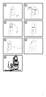
To secure the shock module fasten the lower pin on the spring 

(Figure 4)

 applying 10Nm with a torque wrench and tighten the 3 hex 

screws 

(Figure 8)

. Start with the top hex screw and work down by 

applying 3Nm with a torque wrench. Perform this sequence twice, 
since the upper hex screw will loosen in the first run. Place the bellow 
in the groove on the threaded tube and then tighten the collar over the 
bellow. 

(Figure 7)

WARNING

: Over tightening the hex screws can strip threads and 

cause shock module to bind. 

WARNING

: Make sure the collar covers the edge of the bellow all 

around.

4. 

Applying a Permanent Shock Module Setting 

To permanently fix the shock module, remove the hex screws one by 
one; apply Loctite 243. When finished, re-apply torque of 3Nm on all 
hex screws. Perform this sequence twice, since the upper hex screw 
will loosen in the first run. Failing to apply Loctite 243 to the hex 
screws may result in the shock coming loose. 
Also remove the pin and apply Loctite 243 on threads and tighten with 
10Nm torque. 

DYNAMIC ALIGNMENT
Heel Wedges

Heel wedges influence the heel to toe function. Start altering the heel 
resistance to improve foot response by adding a heel wedge. The small, 
medium and large wedges can be interchanged to customize the 
stiffness and achieve the desired functional characteristics. The wedges 
can be trimmed using sharp scissors to customize stiffness.

Temporary Wedge Placement (Figure 10)

•  Place the wedge in the angle of heel and foot module.
•  Secure in position with tape wrapped around the foot module.

Permanent Wedge Placement

•  Roughen the upper and lower surface of the heel with abrasive paper.
•  Apply adhesive on the lower side of the wedge only.
•  Locate in the foot/heel junction and position before adhesive sets.
•  For split toe feet install the heel wedge then remove a thin slice in the 

middle by cutting with a sharp knife through the split in the carbon 
foot module. 

(Figure 10)

Instant adhesive is necessary to bond the urethane heel wedge. The 
adhesive cures in 15-20 seconds. For removal the adhesive may be 
softened by soaking in acetone or cyanoacrylate adhesive remover.

Heel Divider

The heel divider should be placed in the last third of the split heel part. To 
secure its position a drop of instant adhesive can be used on one side.

Summary of Contents for RE-FLEX SHOCK

Page 1: ...Instructions for Use RE FLEX SHOCKTM...

Page 2: ...se 5 DE Gebrauchsanweisung 9 FR Notice d utilisation 13 ES Instrucciones para el uso 17 IT Istruzioni per l uso 21 DA Brugsanvisning 25 SV Bruksanvisning 29 NL Gebruiksaanwijzing 33 PT Instru es de Ut...

Page 3: ...27 210 8 28 30 221 8 11 16 Max mm 22 24 235 9 25 27 238 9 3 8 28 30 249 9 3 16 10mm 3 8 1 Reference height 10mm 3 8 or 19mm 3 4 Min mm 22 24 251 9 7 8 25 27 255 10 1 16 28 30 274 10 3 4 Max mm 22 24 2...

Page 4: ...4 4 5 6 7 8 9 10...

Page 5: ...t cover use a Flex Foot shoehorn to avoid damage to foot and or foot cover ALIGNMENT RECOMMENDATIONS To ensure optimum function of the foot and pylon use the following guidelines 1 Bench Alignment To...

Page 6: ...IC ALIGNMENT Heel Wedges Heel wedges influence the heel to toe function Start altering the heel resistance to improve foot response by adding a heel wedge The small medium and large wedges can be inte...

Page 7: ...s device meets the requirements of the 93 42 EEC guidelines for medical devices This device has been classified as a class I device according to the classification criteria outlined in appendix IX of...

Page 8: ...g 2 59 P3 ISO 10328 P3 59 kg 3 68 P4 ISO 10328 P4 68 kg 4 77 P4 ISO 10328 P4 77 kg 5 88 P4 ISO 10328 P5 88 kg 6 100 P5 ISO 10328 P5 100 kg 7 116 P5 ISO 10328 P6 116 kg 8 130 P6 ISO 10328 P6 130 kg 9 1...

Page 9: ...sollte auf der Oberseite des Prothesenmoduls und unterhalb des Zehenspalts aufliegen Der Strumpf sollte ab dem Fersenbereich locker sitzen SCHUHL FFEL Wenn Sie die Prothesenabdeckung entfernen und au...

Page 10: ...ss die Kante des Federbalgs vollst ndig bedecken 4 Anwendung des permanenten Sto d mpfermoduls Um das Sto d mpfermodul permanent zu fixieren entfernen Sie zun chst nacheinander die Sechskantschrauben...

Page 11: ...NIGUNG Das Produkt muss nach dem Kontakt mit Wasser Sand oder Schmutz gereinigt werden Die Filter m ssen mit Luftdruck gereinigt werden Abbildung 9 INSTANDHALTUNG Keine Komponentenwartung erforderlich...

Page 12: ...Beschr nkungen siehe schriftliche Herstelleranleitung hinsichtlich des Verwendungszwecks Die obengenannte Norm sieht vor dass die Pr fungsstufen P einer maximalen K rpermasse m in kg zugeordnet werde...

Page 13: ...d et non en dessous de la lame fendue La chaussette doit tre l che pr s de la zone du talon CHAUSSE PIED Il convient d utiliser un chausse pied Flex Foot lors du retrait et de l installation de l enve...

Page 14: ...e du tube filet et serrer la bague par dessus le soufflet L absence de Loctite 243 sur les vis hexagonales pourrait provoquer le desserrage de l amortisseur Retirer galement la goupille et appliquer d...

Page 15: ...4 mm et changer le ressort Figure 4 Appliquer du Loctite 243 sur les filets avant de serrer les goupilles 10 Nm Changer les paliers lisses du ressort Retirer le ressort voir ci dessus et extraire les...

Page 16: ...aines masses corporelles maximales m en kg Dans certains cas toutefois qui sont indiqu s aucune niveau de test n est associ la masse corporelle maximale li e au produit Dans ces cas les charges d essa...

Page 17: ...et n debe descansar sobre la parte superior del m dulo del pie y no bajo el mismo El calcet n debe quedar suelto en la zona del tal n CALZADOR Se recomienda utilizar un calzador Flex Foot para retirar...

Page 18: ...continuaci n apriete el collar n sobre el fuelle La no aplicaci n de Loctite 243 a los tornillos hexagonales puede provocar que el amortiguador se afloje Retire tambi n el pin y aplique Loctite 243 s...

Page 19: ...los pines con una fuerza de torsi n de 10 Nm Cambio de la espiga del muelle Retire el muelle v ase m s arriba y saque las espigas presionando con cuidado Introduzca nuevas espigas y vuelva a unir el m...

Page 20: ...En algunos casos que est n se alados no se ha asignado ning n nivel de prueba al producto relacionado con la masa corporal m xima En estos casos las cargas de prueba se han adaptado adecuadamente sobr...

Page 21: ...a La calza non deve aderire all area del tallone CALZASCARPE Quando si toglie e si mette la cover per piede usare un calzascarpe Flex Foot per evitare di danneggiare piede e o cover ISTRUZIONI PER L A...

Page 22: ...pra il soffietto Se non si applica la Loctite 243 alle viti esagonali il modulo ammortizzante pu allentarsi Rimuovere anche il perno e applicare Loctite 243 sui filetti e serrare con una coppia di 10N...

Page 23: ...v sopra e premere facendo fuoriuscire delicatamente le boccole Inserire le nuove boccole premendo e rimontare la molla v sopra RESPONSABILIT Il produttore consiglia di utilizzare il dispositivo solo a...

Page 24: ...assegnato al prodotto sulla base della massa corporea massima In questi casi i carichi di prova sono stati adattati adeguatamente sulla base del livello di carico specificato Categoria ssur alta atti...

Page 25: ...fjerner og p s tter fodkosmesen skal der anvendes et Flex Foot skohorn for at undg skader p foden og eller fodkosmesen ANBEFALINGER FOR TILPASNING For at sikre at foden og r ret fungerer optimalt ska...

Page 26: ...Loctite 243 p gevindene og sp nd til med et drejningsmoment p 10 Nm DYNAMISK INDSTILLING H lkiler H lkiler p virker h l til t funktionen Start med at ndre h lmodstanden for at forbedre fodens respons...

Page 27: ...e enhed overholder kravene i 93 42 E F retningslinjerne for medicinsk udstyr Denne enhed er klassificeret som en klasse I enhed if lge de klassificeringskriterier der er beskrevet i appendiks IX af re...

Page 28: ...2 59 P3 ISO 10328 P3 59 kg 3 68 P4 ISO 10328 P4 68 kg 4 77 P4 ISO 10328 P4 77 kg 5 88 P4 ISO 10328 P5 88 kg 6 100 P5 ISO 10328 P5 100 kg 7 116 P5 ISO 10328 P6 116 kg 8 130 P6 ISO 10328 P6 130 kg 9 14...

Page 29: ...etiken JUSTERINGSREKOMMENDATIONER F lj nedanst ende riktlinjer f r att s kerst lla optimal funktion p foten och d mparen 1 B nkjustering F r att st lla in l mplig flexion och h lh jd Dela fotens l ngd...

Page 30: ...otst ndet i h len f r att f rb ttra fotens respons genom att l gga till en h lkil Kilarna som finns i storlek liten medium och stor kan bytas ut f r att anpassa styvheten och uppn nskade funktionsegen...

Page 31: ...icintekniska produkter Denna produkt har klassificerats som en klass I enhet enligt klassificeringskriterierna i bilaga IX till direktivet EFTERLEVNAD Denna komponent har testats enligt standarden ISO...

Page 32: ...P3 59 kg 3 68 P4 ISO 10328 P4 68 kg 4 77 P4 ISO 10328 P4 77 kg 5 88 P4 ISO 10328 P5 88 kg 6 100 P5 ISO 10328 P5 100 kg 7 116 P5 ISO 10328 P6 116 kg 8 130 P6 ISO 10328 P6 130 kg 9 147 P6 ISO 10328 P6 1...

Page 33: ...teen De sok hoort los te zitten vanaf het hielgebied SCHOENLEPEL Gebruik tijdens het verwijderen en installeren van de voetovertrek een Flex Foot schoenlepel om schade aan de voet en of voetovertrek...

Page 34: ...alle inbusschroeven opnieuw aan waarbij u 3 Nm toepast Plaats de balg in de groef op de buis met schroefdraad en span de kraag dan aan over de balg Als u geen Loctite 243 op de inbusschroeven toepast...

Page 35: ...s in de veer vervangen Verwijder de veer zie boven en duw de bussen zorgvuldig uit de veer Plaats nieuwe bussen en druk deze aan waarna u de veer opnieuw bevestigt zie boven AANSPRAKELIJKHEID De fabri...

Page 36: ...egewezen aan het product gerelateerd maximale lichaamsmassa In deze gevallen zijn de belastingshypothesen voldoende aangepast aan de hand van het belastingsniveau Categorie ssur hoge activiteit Catego...

Page 37: ...de p e n o por baixo da divis o dos dedos A meia dever permanecer solta na rea do calcanhar CAL ADEIRA Para remover e instalar a cobertura do p utilize uma cal adeira Flex Foot para evitar danos no p...

Page 38: ...o aplicar Loctite 243 poss vel que os parafusos hexagonais no m dulo amortecedor de choque se soltem Remova tamb m o pino e aplique Loctite 243 nas roscas e aperte at 10 Nm ALINHAMENTO DIN MICO Cunhas...

Page 39: ...a mola ver acima RESPONSABILIDADE O fabricante recomenda a utiliza o do componente apenas nas condi es especificadas e para os fins previstos O componente deve ser mantido de acordo com as instru es d...

Page 40: ...roduto tendo em conta a rela o com o ndice de massa corporal m ximo Nestes casos os testes de ensaio foram adaptados de forma adequada em fun o do n vel de carga especificada Categoria ssur atividade...

Page 41: ...41 Re Flex Shock Re Flex 9 Re Flex 1 2 Loctite 243 15Nm 11ft lbs Flex Foot Flex Foot 1 C 1 3 1 3 C 2 4 3 8 5 1 8mm F F 180 3 4 10Nm 3 8 3Nm...

Page 42: ...1 2 7 4 1 Loctite 243 3Nm 7 Loctite 243 Loctite 243 10Nm 10 10 15 20 3 1 ssur 45 52 53 59 60 68 69 77 78 88 89 100 101 116 117 130 131 147 148 166 1 1 2 3 4 5 6 7 8 9 1 2 3 4 5 6 7 8 9 2 3 4 5 6 7 8...

Page 43: ...P m kg P m in kg ssur kg 1 52 P3 ISO 10328 P3 52 kg 2 59 P3 ISO 10328 P3 59 kg 3 68 P4 ISO 10328 P4 68 kg 4 77 P4 ISO 10328 P4 77 kg 5 88 P4 ISO 10328 P5 88 kg 6 100 P5 ISO 10328 P5 100 kg 7 116 P5 IS...

Page 44: ...44 Re Flex Re Flex 9 Re Flex 1 B 243 15Nm 11ft lbs 1 3 3 2 D 3 H E 8mm F F 180 3 10Nm D 3 H...

Page 45: ...45 3Nm 7 4 243 3Nm 243 243 10Nm 10 J 15 20 Ossur 45 52 53 59 60 68 69 77 78 88 89 100 101 116 117 130 131 147 148 166 1 1 2 3 4 5 6 7 8 9 1 2 3 4 5 6 7 8 9 2 3 4 5 6 7 8 9...

Page 46: ...m CE 93 42 EEC ISO 10328 200 ISO 10328 P m kg P ssur Kg 1 52 P3 ISO 10328 P3 52 kg 2 59 P3 ISO 10328 P3 59 kg 3 68 P4 ISO 10328 P4 68 kg 4 77 P4 ISO 10328 P4 77 kg 5 88 P4 ISO 10328 P5 88 kg 6 100 P5...

Page 47: ...47 ssur Kg 7 116 P5 ISO 10328 P6 116 kg 8 130 P6 ISO 10328 P6 130 kg 9 147 P6 ISO 10328 P6 147 kg...

Page 48: ...prodotti Ossur sono utilizzati in combinazione con altri componenti Ossur consigliati Qualora una parte strutturale del dispositivo mostri segni di usura anche meccanica informare l utente di sospende...

Page 49: ...1 Ossur Ossur...

Page 50: ...W16 B info europe ossur com No 1801 Hongmei Road 200233 Shanghai China ssur Deutschland GmbH Tel 86 21 6127 1707 Augustinusstrasse 11A asia ossur com 50226 Frechen Deutschland Tel 49 0 2234 6039 102...

Reviews: