ORTECO IIa Series Use And Maintenance Manual Download Page 69

63

English language

Use and maintenance

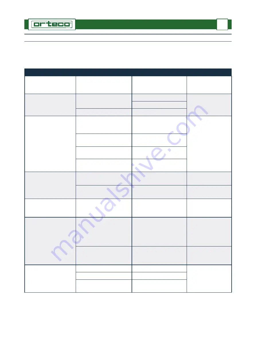
BREAKDOWN INFORMATION

8

Safety advice in case of faults

Repairs that require specific technical competence or special skills must be carried 
out only by an authorised service centre.

Fault

Likely cause

Solution

Reference

Hammer percussion is not 
regular

Cold oil

Repeat machine movements 
several times to heat the oil

Weak hammer percussion

Flat accumulator

Recharge

Contact an authorised 
service centre

(*)

Damaged accumulator

Replace the membrane

Percussion gets blocked

Excessive oil counter pressure 
in return pipe

Restore the correct counter 
pressure

Contact an authorised 
service centre

Excessive oil delivery

Restore the correct oil 
delivery

Loose nuts of the percussion 
hammer’s tie rod

Tighten the nuts

Faulty hydraulic system

Restore the hydraulic system

The engine switches off 
immediately after start-up

The emergency button has 
been accidentally pressed

Deactivate the emergency 
button

The electrical system of the 
emergency button in faulty

Repair the fault

Contact an authorised 
service centre

Locking machine 
movements

Maximum pressure valves of 
the distributors clogged with 
dirt

Clean the valves

Contact an authorised 
service centre

The accessory does not 
switch on

The hydraulic supply by-pass 
valve lever is in the hammer 
activation position

Turn the valve lever to the 
correct position

The accessory does not work 
correctly

See the instruction 
manual of the accessory’s 
manufacturer

The machine does not 
have the original operating 
speed and percussion 
power

Damaged pump

Replace the pump

Contact an authorised 
service centre

Damaged PTO

Replace the PTO

Main pressure valve not 
calibrated correctly

Set correct calibration

(*)  If the accumulator has worked for a prolonged period at a pressure below 20 bar, replace the 

membrane

Summary of Contents for IIa Series

Page 1: ...milia Bo Italia Tel 39 051 731051 Fax 39 051 731925 mail orteco orteco com www orteco com SELF PROPELLED TRACKED PILE DRIVER USE AND MAINTENANCE MANUAL Manual code 130701 Language english Edition 07 2...

Page 2: ......

Page 3: ...sting track tension 22 Advice for handling and transportation 17 Aim of the manual 1 Analytical index III Annexed documentation 3 C Checking and cleaning the supplementary air filter 57 Cleaning and l...

Page 4: ...make holes using the corer 40 Procedure to make holes using the drill 47 R Radio control 69 Re commissioning 52 Refuelling 52 Replacing hosing 66 Replacing supplementary air filter cartridges 65 Repla...

Page 5: ...4 T Technical assistance procedure 3 Technical characteristics 9 Track gearmotor oil level check 59 Track tension check 60 Transportation procedure 17 U Use in cold environmental conditions 31 Using t...

Page 6: ......

Page 7: ...the instructions The manufacturer reserves the right to make changes to the manual without prior notice with the exception of changes concerning the level of safety The manual must be kept for future...

Page 8: ...up the machine The plate contains all the information to identify the machine and the manufacturer Identification plate A Manufacturer s details B Machine model C Type of machine D Serial number E Yea...

Page 9: ...be held responsible for the following use of the machine by untrained and or unauthorised personnel improper use of the machine failure to carry out maintenance unauthorised modifications or repairs...

Page 10: ...ncreases the machine s functionality for specific operations The accessory must be requested by the customer when placing the order Supplement component or unit that completes the machine which is not...

Page 11: ...e machine to drill holes in conglomerates in the ground and in rocky ground One operator is sufficient to operate the machine said operator must have the necessary requisites to use the machine in tot...

Page 12: ...xtraction clamp corer and drill must not be used to drive piles Operator training The operator has the task of carrying out all the operations related to the use of the ma chine and ordinary maintenan...

Page 13: ...se valves are installed on the jacks 1 and 2 C Maximum pressure valve this limits maximum operating pressure to prevent over loading of the hydraulic system The valve installed on each hydraulic distr...

Page 14: ...f they are not replace them with new ones maintaining the original location on the machine The illustrations show the position of the safety and information signs on the machine The meaning of each si...

Page 15: ...ve 20 This shows the battery cut off device 21 This shows the direction of movement and the relevant manoeuvres of the pile driver control levers 22 This shows the connection of the high pressure deli...

Page 16: ...ound level measured in operating condition when driving metal piles is shown in the table The measurement has been carried out in compliance with the UNI EN 11201 2009 UNI EN 996 2009 standards using...

Page 17: ...must be programmed to reduce the exposure to noise Gas emissions During operation and or when standing still the machine emits the toxic gases listed be low Carbon monoxide generated by the exhaust of...

Page 18: ...ced in compliance with the harmonized standard EN ISO 12100 1 2009 Machinery Safety basic concepts design general principles Part 1 Basic therminology methodology EN ISO 12100 2 2009 Machinery Safety...

Page 19: ...cedure to make holes using the corer C Boring device to make circular holes on hard and compact surfaces cement rock us ing a tool with a combined rotation and percussion action For technical informat...

Page 20: ...e that stops the hammer s down stroke C Column verticality automatic device to automatically place the column in vertical position independently from the gradient of the ground D Compressed air circui...

Page 21: ...art or use the machine in poorly ventilated areas If necessary adopt all nec essary precautions to prevent build ups of machine exhaust gas Safety instructions for use and operation The operator must...

Page 22: ...the most important safety elements Maintenance schedule operations must be carried out at the set intervals and in the manner foreseen by the manufacturer Formaintenanceoperationsthatrequirespecialequ...

Page 23: ...the local laws in force If necessary ramps can be used to load unload the machine from the transport vehi cle the ramps must be in good condition and with a suitable capacity Transportation procedure...

Page 24: ...as outlined below 1 Check the weight of the machine to be lifted in the Technical information chapter to make sure the lifting means is suitable 2 Fix the lifting ropes to the eyebolts marked A indic...

Page 25: ...ake sure the lifting means is suitable 4 Fasten the ropes to the bow shackles A indicated by a special sign The illustration shows the harnessing points and lifting procedure Procedure for getting on...

Page 26: ...ust the width of the ramps so that the machine weight is evenly distributed 4 Move up onto the transport means with minimum forward speed 5 Switch off the engine and remove the ignition key 6 Place th...

Page 27: ...hine see Starting the engine 4 Position the machine centrally to the ramps and if necessary adjust the width of the ramps so that the machine weight is evenly distributed 5 Move off the transport mean...

Page 28: ...by maximum one turn and never un screw the lubricator Proceed as outlined below 1 Stop the machine on solid and even ground 2 Switch off the engine and remove the ignition key and keep it in a safe p...

Page 29: ...pth see Pile driving procedure 3 Stop the percussion and rest the hammer on the pile head 4 Loosen the screws A 5 Adjust the device B at the centre line of the proximity sensor C as shown in the fig u...

Page 30: ...p the tool in contact with the ground 4 Loosen the screws A 5 Adjust the device B at the centre line of the proximity sensor C as shown in the fig ure 6 Tighten the screws A 7 Turn the selector D to t...

Page 31: ...nd rest the hammer on the pile head 4 Activate the emitter of the laser device 5 Turn the selector A to the laser position 1 to activate the device 6 Position the laser emitter B at a distance of at l...

Page 32: ...er B at a maximum distance of 100 150 m from the pile driver 7 Adjust the laser emitter B at a height from the ground similar to that of the receiver and is such a way that there are no obstacles betw...

Page 33: ...gorges ditches filled excavations and ridges rough ground wet or muddy ground On sloping ground move and operate the machine only within the limits foreseen by the manufacturer see Technical characte...

Page 34: ...Signal light red this shows there is insufficient engine oil pressure F Signal light red this shows that the engine air filter is clogged G Signal light red this shows the engine is overheating H Sig...

Page 35: ...Controls to run the machine A Lever to activate the left track Sx Move the lever to position 1 to move the track in direction I Move the lever to position 2 to move the track in direction II When the...

Page 36: ...e slow floating lowering of the percussion hammer Position D2 to activate the lifting of the percussion hammer Neutral position D0 this deactivates the up and down movements of the percussion hammer E...

Page 37: ...boring device drill etc see the procedure for the use of the accessory installed on the machine Position L1 to activate the percussion hammer Position L0 to stop the percussion hammer Position L2 if...

Page 38: ...and the electrical sys tem 3 Check that the fuel valve T is open 4 Position the accelerator lever R about half way 5 Turn the ignition key B by one click position I 6 The signal lights D and E switch...

Page 39: ...motor is on the signal lights D and E switch off and the buzzer Q stops Starting the engine with the auxiliary battery Danger Warning Do not cause sparks or use naked flames near the batteries Avoid d...

Page 40: ...rator For transfers at the work site put the pile driver in resting position C and control the ma chine from the position E foreseen for the operator Proceed as outlined below 1 Start the engine see S...

Page 41: ...und the operator s experience and good sense prevail over any rule Proceed as outlined below 1 Start the engine see Starting the engine Danger Warning On sloping ground travel at minimum speed to prev...

Page 42: ...into the ground the percussion hammer must be manually placed in a perfectly vertical position see Operation controls or automatically see Using the verticality system To manually place the column in...

Page 43: ...until the head of the pile is inside the grooved profile of the stroke plate and then move it to the floating position B3 Caution Care Make sure that the automatic verticality system is disabled befo...

Page 44: ...stand at the side of the percussion hammer see figure Danger Warning Fit the clamp with the machine parked on flat and stable ground the engine off and the percussion hammer at minimum distance from...

Page 45: ...ting the machine 5 Move the lever N to lower the percussion hammer until the clamp is positioned on the end of the hammer 6 Lock the grip of the clamp on the pile using the lever P 7 Move the lever N...

Page 46: ...measures and use suitable equipment to avoid accidents that could injure the people in charge of the operation and people nearby Fitting the corer To fit the corer proceed as outlined below 1 Lower t...

Page 47: ...he tool B near the surface to be drilled 3 Place the column in a perfectly vertical position To manually position the column in vertical position use the levers H and M Check the verticality using the...

Page 48: ...imum distance from the ground Arrange appropriate safety measures and use suitable equipment to avoid accidents that could injure the people in charge of the operation and people nearby Fitting the bo...

Page 49: ...ercussion hammer slightly and unscrew the safety lock pin Y 13 Move the lever R to lower the boring device to the ground 14 Stop the machine see Operational stop 15 Fit the half bushings L onto the pi...

Page 50: ...evel gauge C To automatically place the column in vertical position see Using the automatic verti cality system 4 Move levers S and T to slightly change the position of the tool 5 Switch on the supply...

Page 51: ...to unblock the tool from the hole After having unblocked the tool move lever V to the disabled position V0 to stop the counter rotation Move the lever R to position R1 to remove the tool from the hole...

Page 52: ...he ISO VG100 type Removing the boring device To remove the boring device carry out the fitting operations described above in reverse order Boring device maintenance For maintenance operations refer to...

Page 53: ...d the percussion hammer at the necessary distance from the ground to fit the tool Arrange appropriate safety measures and use suitable equipment to avoid accidents that could injure the people in char...

Page 54: ...support A and tighten the screws B to fix it to the percussion hammer 2 Fit the head C of the drill on the support A 3 Insert the pin D and the lock pin E 4 Lift the percussion hammer the bare minimu...

Page 55: ...ivate the tool forward 7 Once the required depth has been reached move the lever D to position D0 to manu ally stop tool rotation or activate the automatic stop devices PROXIMITY or laser 8 Move the l...

Page 56: ...lumn and sends the signal to the electronic control unit which switches on the red signal lights and the green signal light Controls and signals gauges A Key switch to activate the automatic verticali...

Page 57: ...tions described 1 Position the column near the pile to be driven into the ground see Pile driving procedure 2 Turn the key of the switch A to position I One or both the signal lights B and C may switc...

Page 58: ...n the machine is not going to be used for long periods of time proceed as follows 1 Wash the machine completely 2 Grease the machine see Lubrication diagram 3 Fix any oil leaks hydraulic and engine ci...

Page 59: ...e 6 Remove the ignition key C from the dashboard and keep it in a safe place 7 Close the dashboard guard E and assess the need to padlock it to avoid tampering of the controls and prevent unauthorised...

Page 60: ...visibility conditions Working at night or in low visibility conditions increases the risks that derive from the use of the machine In case of work at night or in low visibility conditions use the swit...

Page 61: ...ication diagram See Nut and bolt check Contact an authorised service centre Every 100 hours of work Track gearmotor Percussion hammer lifting chain Slide Inside of the column Oil level check Oil chang...

Page 62: ...own in the illustration Before lubricating clean the components concerned and the greasing nipples to prevent contamination of the lubricant The lubricants indicated are factory fill lubricants For eq...

Page 63: ...debris suspended in the air from seriously damaging the engine In certain operating conditions dust dirt and debris the air filter may need to be checked and cleaned more frequently Use the valve A to...

Page 64: ...y along the folds of the fil tering material from the inside outwards Be careful not to damage the folds of the filtering ele ment Theprimaryfiltercanbecleaneduptosixtimes ifcleaned and checked correc...

Page 65: ...d store it safely 3 Unscrew a cap A B and check that the oil is level with the bottom edge of the hole 4 If necessary top up the oil to the correct level from the same hole 5 After topping up screw th...

Page 66: ...ecessary adjust the track to the correct tension see Adjusting track tension Hydraulic oil level check Proceed as outlined below Caution Care Slowly unscrew the cap and discharge the pressure inside t...

Page 67: ...oded etc it must be replaced immediately see Replac ing the chain Proceed as outlined below 1 Stop the machine on solid and even ground 2 Switch off the engine and remove the ignition key and keep it...

Page 68: ...1350 0 1850 0 2250 0 Hydraulic oil suitable for room temperature of 20 to 40 C Brand IP AGIP MOBIL SHELL Type IP HYDRUS HI 46 ENI ARNICA 46 MOBIL DTE 10 ECEL 46 SHELL TELLUS T 46 Grease Brand IP AGIP...

Page 69: ...ic system The engine switches off immediately after start up The emergency button has been accidentally pressed Deactivate the emergency button The electrical system of the emergency button in faulty...

Page 70: ...r material near the moving parts or in risk areas The components removed and waste material must disposed of in compliance with the laws in force concerning waste collection sorting and disposal Repla...

Page 71: ...ow 1 Position a container of adequate capacity under the filter to collect the oil 2 Clean the filter s outer surfaces accurately 3 Unscrew the filter unit B 4 Slide out the worn or clogged filter car...

Page 72: ...nd move the shift control levers in both direc tions Unscrew the hosing fittings and collect the oil in a suitable container Replace hosing and tighten the fittings Replacing the track reduction gear...

Page 73: ...ely When replacing the chain replace the connection link and the fixing pins that connect the chain to the anchorage blocks The chain must be in any case replaced after 1000 hours of work The chain mu...

Page 74: ...ntly move the lever D and carefully lower the percussion hammer 9 Fit the screws B and tighten the nuts A 10 Fit the guide plate H 11 Replace the matrix G with the stroke plate Scrapping the machine S...

Page 75: ...osition B the percussion hammer floating descent is activated 3 Lever to shift the column transversally to the machine Position A to retract the column Position B to extend the column 4 Lever to tilt...

Page 76: ...position B to move the right Dx track back wards 6 Lever to activate the outrigger jack Position A to lift the jack rod off the ground Position B to lower the jack rod on the ground 7 Lever to activat...

Page 77: ...e 16 Two way switch to switch the functions described I from working resting position to movement of the left track and vice versa II from longitudinal shifting of the column to movement of the right...

Page 78: ...he European Union 3 1 Physical chemical dangers Important hazards Product with a low risk of fire It can create flammable mixtures or burn only if heated above its flash point 3 2 Dangers for human he...

Page 79: ...taneous vomiting transport the victim to a hospital 5 Fire fighting measures General information Shut off source of product if possible If possible move containers and drums away from danger area Exti...

Page 80: ...ntrol of exposure General informations In case the concentration of the product or any constituent is above the exposure limits and if plant characteristics work procedures and other means are not abl...

Page 81: ...92 Auto ignition temperature 300 C DIN 51794 Explosion limits Lower Not determined Upper Not determined Partition coefficient P o w Not determined DMSO extract of base stock 3 wt IP 346 92 10 Stabili...

Page 82: ...of the product either new or used by discharging into sewers tunnels lakes or water courses Deliver to a qualified official collector European Waste Catalogue Code 13 01 10 Ref 2001 118 CE This code i...

Page 83: ...mproper use Other uses of the product Do not use the product for any purposes that have not been advised by the manufacturer In that case the user could be exposed to unforeseeable dangers Document re...

Page 84: ...78 ENCLOSURES A English language Use and maintenance...

Page 85: ...79 ENCLOSURES A English language Use and maintenance...

Page 86: ...80 ENCLOSURES A English language Use and maintenance...

Page 87: ...81 ENCLOSURES A English language Use and maintenance...

Page 88: ...82 ENCLOSURES A English language Use and maintenance...

Page 89: ...83 ENCLOSURES A English language Use and maintenance...

Page 90: ...84 ENCLOSURES A English language Use and maintenance...

Page 91: ...85 ENCLOSURES A English language Use and maintenance...

Page 92: ...86 ENCLOSURES A English language Use and maintenance...

Page 93: ...lammable mixtures or burn only if heated at temperatures which are higher than normal ambient levels 2 Dangers for human health Skin contact Prolonged and repeated skin contact especially if hygiene p...

Page 94: ...ained in this product have a value 3 wt of DMSO extract according to IP 346 92 note L Dir 94 69 CE 4 First aid measures Skin contact Take off contaminated clothing and shoes Wash thoroughly with soap...

Page 95: ...il resistant containers Clean contaminated area Dispose of according to local regulations Water Confine the spillage Remove from surface by skimming or suitable absorbents Collect recovered product an...

Page 96: ...de of PVC can be used for limited periods Gloves made of Neoprene or natural rubber latex have inadequate resistance Use gloves respecting all the conditions and within the limits set by the manufactu...

Page 97: ...d to the classification of the product R 38 Irritating to skin R 41 Risk of serious damage to eyes R 50 53 Very toxic to aquatic organisms may cause long term adverse effects in the aquatic environmen...

Page 98: ...d to the classification of the product R 38 Irritating to skin R 41 Risk of serious damage to eyes R 50 53 Very toxic to aquatic organisms may cause long term adverse effects in the aquatic environmen...

Page 99: ...d to the classification of the product R 38 Irritating to skin R 41 Risk of serious damage to eyes R 50 53 Very toxic to aquatic organisms may cause long term adverse effects in the aquatic environmen...

Page 100: ...ated at temperatures which are higher than normal ambient levels 2 Dangers for human health Skin contact Prolonged and repeated skin contact especially if hygiene practices are poor may cause reddenin...

Page 101: ...part If inflammation or irritation persists seek medical advice I nges tion Do not induce vomiting to avoid aspiration into the lungs If the person is conscious rinse mouth with water without swallowi...

Page 102: ...regulations Do not use solvents or dispersants 7 Handling and storage Storage Keep away from sources of ignition Storage temperature ambient to 55 C max Handling Store the product in cool well ventila...

Page 103: ...mediately in case of cuts holes or other signs of damages or degradation If necessary refer to the EN 374 standard Hygiene measures Avoid contact with skin and eyes Do not breathe vapours or mists Do...

Page 104: ...nificant constituents of the product should be considered as inherently biodegradable but not readily biodegradable and they may be moderately persistent particularly in anaerobic conditions Toxicity...

Page 105: ...ersion 1 03 Date 17 08 2010 This information relates only to the specific product and may not be valid if the product is used in combination with any other material or in any process The informations...

Page 106: ...Version 1 03 Date 17 08 2010 This information relates only to the specific product and may not be valid if the product is used in combination with any other material or in any process The informations...

Page 107: ...arefully follow the safety instructions described herein and the regulations on accident prevention at work Maintenance sheets after 100 hours of work Date of operation ______ _______ _____ Descriptio...

Page 108: ...of operation ______ _______ _____ Description of operation Stamp of the authorised service centre Signature of the technician Maintenance sheets after 500 hours of work Date of operation ______ _____...

Page 109: ...of operation ______ _______ _____ Description of operation Stamp of the authorised service centre Signature of the technician Maintenance sheets after 800 hours of work Date of operation ______ _____...

Page 110: ...of operation ______ _______ _____ Description of operation Stamp of the authorised service centre Signature of the technician Maintenance sheets after 1200 hours of work Date of operation ______ ____...

Page 111: ...of operation ______ _______ _____ Description of operation Stamp of the authorised service centre Signature of the technician Maintenance sheets after 1500 hours of work Date of operation ______ ____...

Page 112: ...of operation ______ _______ _____ Description of operation Stamp of the authorised service centre Signature of the technician Maintenance sheets after 1800 hours of work Date of operation ______ ____...

Page 113: ...A English language Use and maintenance Maintenance sheets after 2000 hours of work Date of operation ______ _______ _____ Description of operation Stamp of the authorised service centre Signature of...

Page 114: ...108 ENCLOSURES A English language Use and maintenance...

Reviews: