


SMTS II for GPC-XP Technical Guide
MAIN SCREEN FUNCTIONS
11
Setting the System Clock
Set Time and Date
When you fi rst power up your System Manager TS II, you will need
to change the day of the week, the time, and the month, day, and
year to the current time and date. If your system has been turned
off or has been down for a long time, you may have to do the same,
although the time and date can maintain itself for several days. Any
level of user can change the time and date settings.
The day of the week, the time, and the date appear at the top right
on the
Main Screen
. See
Figure 6, page 9
.
From the
Main Screen
,
touch
the
< Set Time &
Date>
icon. The
Set Time & Date Screen
will appear.
See
Figure 10
.
In the example above, the current time and date is 2:12 PM, January
16, 2014. There is no day of the week selected yet.
Set Day of the Week:
Select the day of the week by simply
touching
your selection. The day of the week text will change from
white to blue.
Set Hour, Minute, Month, Day, and Year:
Touch
the blue high-
lighted box to have each selection screen appear. See
Figures 10
&
11
. Read the instructions on each screen for entering data.
Broadcast:
When you are fi nished setting the clock,
touch
the
<Broadcast>
button to broadcast the Time and Date to all Units.
The following message will appear:
Figure 10: Set Time & Date Screen
Back
Set Time & Date
Broadcast
System Manager Settings
Mon
Tue
Wed
Hour
Minute
Month
Day
Year
14
12
1
16
14
Sun
Thu
Sun
Thu
Fri
Sun
Fri
Sat
Sun
Sat
Esc
1
2
3
4
7
-
0
.
9
8
5
6
OK
<<
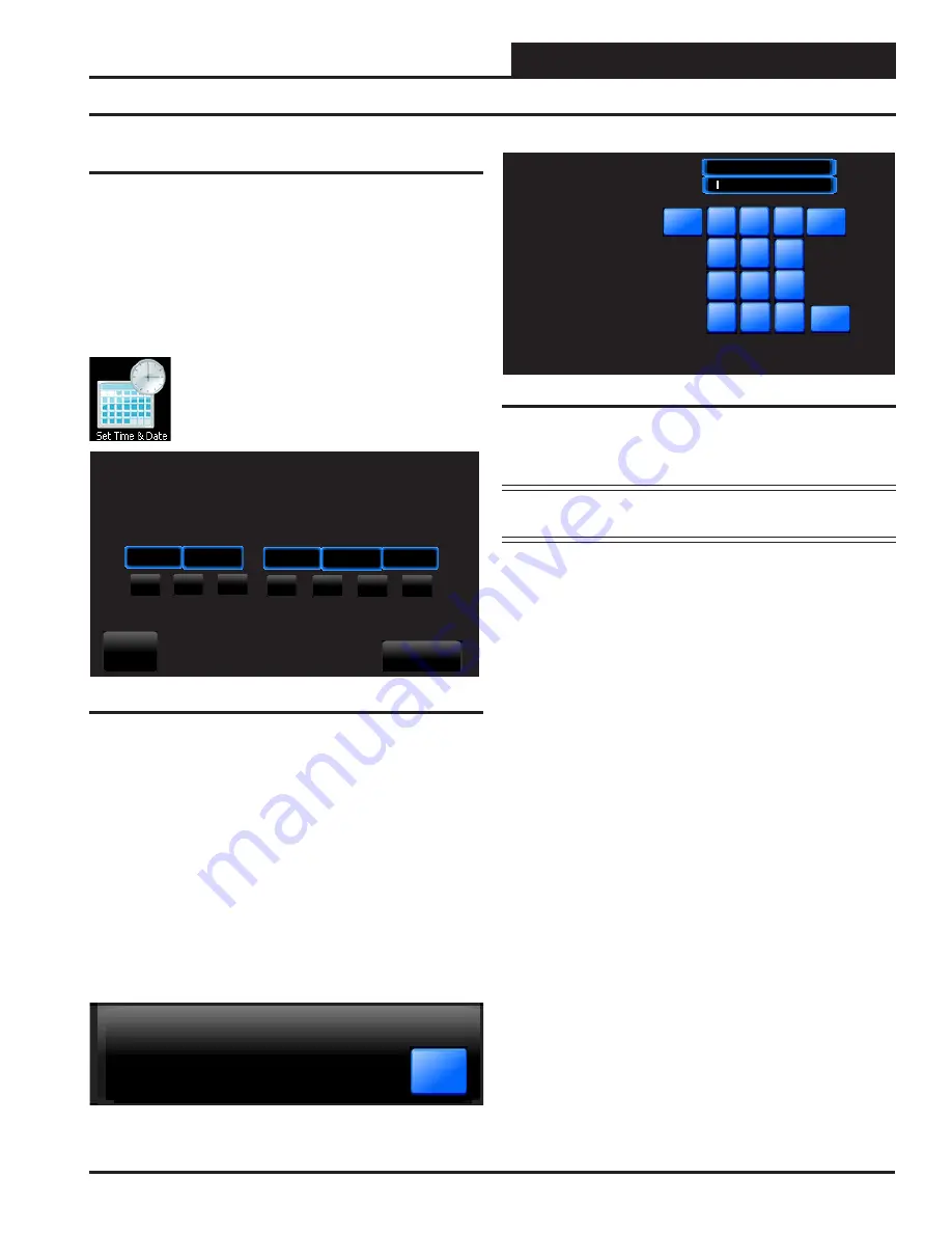
Currently: 10
DATA ENTRY
Set Clock Hour
Enter the Current Hour in
24 hour military format.
Example:
5:00 AM = 5
5:00 PM = 17
Hi Limit: 23
Lo Limit: 0
Figure 11: Set Clock Hour
Set Clock Hour:
Touch
the number buttons to enter the current hour
in 24 hour military format. Valid entries are from 0-23.
Press
<OK>
.
NOTE:
See
Appendix on page 20
for a Military Time
Conversion table.
Set Clock Minute:
Touch
the number buttons to enter the current
minutes. Valid entries are from 0-59.
Press
<OK>
.
Time & Date Broadcast to All Units.
OK
Set Clock Month:
Touch
the number buttons to enter the current
month. Valid entries are from 1-12.
Press
<OK>
.
Set Clock Day:
Touch
the number buttons to enter the current day
of the month. Valid entries are from 1-31.
Touch
<OK>
.
Set Clock Year:
Touch
the number buttons to enter the current year.
Valid entries are from 0-99.
Touch
<OK>
.
Note:
The year is based
on the current century; therefore, 14 = 2014. If you enter more than
two digits, e.g. 2014, the system will not recognize your entry.


