6 Connection
!
32
!
24 VDC
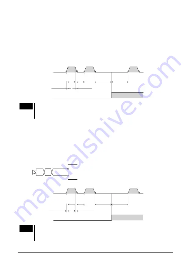
The controller pulses are connected to the PLS24+ input (pin No.2) or the PLS
!
input (pin No.9), and the rotation direction is connected to the DIR24+ input (pin
No.10) or DIR
!
input (pin No.11).
!"
When the DIR input is ON, a fall of the PLS input from ON to OFF will rotate the
motor one step in the CW direction.
!"
When the DIR input is OFF, a fall of the PLS input from ON to OFF will rotate
the motor one step in the CCW direction.
90%
10%
2 µs
or more
2 µs
or more
1 µs or less
1 µs or less
DIR input
CW
CCW
ON
OFF
ON
OFF
PLS input
10 µs
or more
10 µs
or more
ON: 21.6 to 26.4 V
OFF: 0 to 1 V
Note
The interval for switching the motor direction represents the response time
of the circuit. Set this interval to an appropriate time after which the motor
will respond.
Line driver input
The controller pulses are connected to the PLS+ input (pin No.1) or the PLS
!
input
(pin No.9), and the rotation direction is connected to the DIR+ input (pin No.3) or
DIR
!
input (pin No.11).
!"
When the DIR input is ON, a fall of the PLS input from ON to OFF will rotate the
motor one step in the CW direction.
!"
When the DIR input is OFF, a fall of the PLS input from ON to OFF will rotate
the motor one step in the CCW direction.
1, 3
9, 11
90%
10%
1 µs
or more
1 µs
or more
1 µs or less
1 µs or less
DIR input
CW
CCW
ON
OFF
ON
OFF
PLS input
10 µs
or more
10 µs
or more
ON: 3.0 to 5.25 V
OFF: -5.25 to 1 V
Note
The interval for switching the motor direction represents the response time
of the circuit. Set this interval to an appropriate time after which the motor
will respond.


