6 Connection
!
31
!
6.6 About input/output signals
!"
Input signals
The signal state represents the “ON: Carrying current” or “OFF: Not carrying
current” state of the internal photocoupler.
•
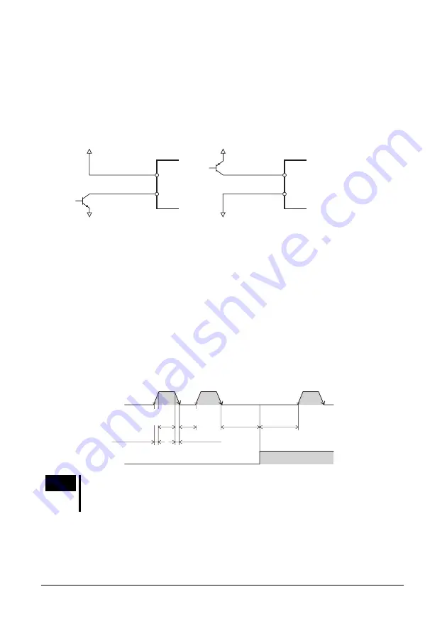
Example of connection with a
current source output circuit
5 VDC, 24 VDC
1, 2, 3, 5, 10
4, 9, 11, 12
1, 2, 3, 5, 10
4, 9, 11, 12
5 VDC, 24 VDC
0 V
0 V
•
Example of connection with a
current sink output circuit
!"
PLS (pulse) input, DIR (rotating direction) input
Either 5 or 24 VDC can be used as the signal voltage for the PLS input, and DIR
input.
Line driver input is also supported.
5 VDC
The controller pulses are connected to the PLS+ input (pin No.1) or the PLS
!
input
(pin No.9), and the rotation direction is connected to the DIR+ input (pin No.3) or
DIR
!
input (pin No.11).
!"
When the DIR input is ON, a fall of the PLS input from ON to OFF will rotate the
motor one step in the CW direction.
!"
When the DIR input is OFF, a fall of the PLS input from ON to OFF will rotate
the motor one step in the CCW direction.
2 µs
or more
90%
10%
2 µs
or more
1 µs or less
1 µs or less
DIR input
CW
CCW
ON
OFF
ON
OFF
PLS input
10 µs
or more
10 µs
or more
ON: 3.0 to 5.25 V
OFF: 0 to 1 V
Note
The interval for switching the motor direction represents the response time
of the circuit. Set this interval to an appropriate time after which the motor
will respond.


