background image

11

OVErVIEW

7 How to Install

CAUTION: keep out of reach of children.

Parent Unit

1.   Place the parent unit in a place that will have 

clear reception with your camera(s).

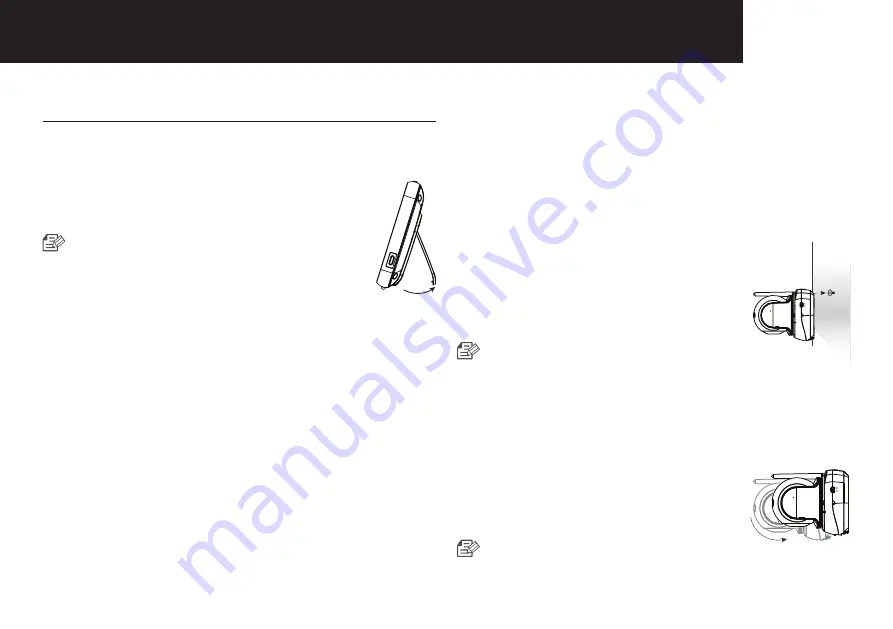
2.  Extend the stand.


   Do not use excessive force when 

extending stand.

DC IN 5V

Camera Unit

Before you install the camera, carefully plan where and 

how it will be positioned, and where you will route the cable 

that connects the camera to the power adaptor.

Before starting permanent installation, verify its performance 

by observing the image on the parent unit when camera 

is positioned in the same location/position where it will be 

permanently installed and the parent unit is placed in the 

location where it will be used most of the time.

Installation Warnings

Aim the camera(s) to best optimize the viewing area: Select 

a location for the camera that provides a clear view of the 

area you want to monitor, which is free from dust, and is 

not in line-of-sight to a strong light source or direct sunlight.
Avoid installing the camera where there are thick walls or 

obstructions between the camera and the parent unit.

STRANGULATION  HAZARD  - Keep  cord  out  of child's 

reach. NEVER place camera or cords within 1 meter of cot 

or playpen. Never use extension cords with AC Adaptors.

Only use the AC Adaptors provided.

1.   Carefully unpack the camera. 

If you are installing additional, please see the pairing 

camera section of this manual for details on installation.

2.   Wall mounting the camera.

Mark the position of the screw hole 

on the wall, and drill hole and insert 1 

screw, then firmly attach the camera to 

the wall by placing the stand over the 

installed screw and pushing the base 

downwards.


   To install on a concrete wall, drill  

a hole and use plastic anchor to fix.

   Use the drilling template to drill holes on the wall 

for camera installation. (Page 18)

   The camera can also be placed on a flat surface, 

such as a table or shelf with no mounting hardware 

required.

3.   Adjust the viewing angle of the camera.


Use the pan and tilt controls on the 

parent unit to adjust the viewing angle 

of the camera.


   Adjusting the camera with excessive 


force may damage the unit.

Summary of Contents for Secure875

Page 1: ...Baby Monitor Secure875 User Guide KEEP THIS USER GUIDE FOR FUTURE REFERENCE Always retain your proof of purchase in case of warranty service www oricom com au...

Page 2: ...at s Included Package Contents 3 Getting Started Functional Description 3 Powering your monitor 3 Operating the System 3 Viewing Mode Display Indicator Description 6 How to use the indicator 6 Menu Op...

Page 3: ...on it for your baby s wellbeing It is important that you regularly check on your baby personally Make sure the baby unit parent unit and mains adaptor cables are kept out of reach of your baby and ot...

Page 4: ...s with water and seek medical assistance Do not modify remanufacture attempt to insert foreign objects into the battery or immerse or expose it to water or other liquids Batteries may explode if damag...

Page 5: ...comes with the following Camera Unit Parent Unit User Manual Camera Unit Power Adaptor Parent Unit Power Adaptor Plastic anchor 1EA Screw 1EA Check your package to confirm that you have received the c...

Page 6: ...unit battery should be recharged Battery Life The rechargeable battery pack supplied can be charged and discharged hundreds of times however it will eventually wear out and lose its ability to hold a...

Page 7: ...d then the screen is split in 2 if more than 2 cameras are paired the screen is split into 4 In split screen mode there is no audio from any of the camera units To scan between paired cameras press th...

Page 8: ...viewed camera Press icon on the parent unit to zoom back out 6 Night Vision Indicator Indicates night vision is activated on the viewed camera Note night vision mode is in black and white only 7 VOX O...

Page 9: ...he monitor volume 4 Zoom In Zoom Out Select to digitally Zoom in and out Zoom icon will show when in x1 and x1 5 Zoom Zoom out icon will show when in x2 Zoom 5 Lullaby Press the icon to turn on and tu...

Page 10: ...ion is selected the monitor will be triggered by lower audio levels than when High Sound Level Detection is selected Audio Only Mode Video will time out after 30 seconds audio will remain on Continuou...

Page 11: ...pening the box fully charge the parent unit before use After initial charge recharge as required Front Controls DC IN 5V 1 2 3 1 Front Cover 2 Button 3 Rubber Feet Back Controls 4 5 7 8 9 6 4 Rear Cov...

Page 12: ...3 2 4 5 9 7 8 10 6 1 Top Cover 2 Deco part 3 Camera Cover 4 IR Window 5 Middle Cover 6 Night light push to turn on off 7 Antenna 8 Power Switch 9 Bottom Cover 10 CDS Sensor Side Bottom Controls DC IN...

Page 13: ...ect sunlight Avoid installing the camera where there are thick walls or obstructions between the camera and the parent unit STRANGULATION HAZARD Keep cord out of child s reach NEVER place camera or co...

Page 14: ...Operating Temperature Range 0 C 40 C Operating Humidity Range 85 RH Environment Rating Indoor use only Pan Angle 300 Tilt Angle 110 Parent Unit Display Type Size Colour TFT 5 Resolution 800X480 Digit...

Page 15: ...it 2 Remove obstructions between the parent unit and camera 3 Adjust the parent unit antenna to vertical position No sounds even with both units turned on 1 Make sure that the power adaptor is connect...

Page 16: ...n performance No change to the conditions of this Express Warranty is valid unless it is made in writing and signed by an authorised representative of Oricom Express Warranty Australia This Express Wa...

Page 17: ...with you if your product qualifies under warranty If so they will give you a Product Return Authorisation number We will then email or fax a Return Authorisation form and a Repair Notice if necessary...

Page 18: ...user generated data such as stored telephone numbers text messages and contact information Please ensure that you have made a copy of any data saved on your goods before sending for repair Please also...

Page 19: ......

Page 20: ...CAMERA FRONT Screw holes for the Camera installation TEMPLATE This template is used to install the camera on the wall...

Page 21: ...and efficiently Oricom Support Australia For all product enquiries troubleshooting or to discuss the range of Oricom products feel free to contact Oricom or visit our website for answers to frequently...

Reviews: