background image

OPUS


ATX/ITX DC-DC 90W Power Supply User Guide


Solutions, Inc. 


 www.opussolutions.com


©

 OPUS Solutions, Inc. 2002,2003; UG-DCX3.xx09   14-MAR-04


7


Testing the PC with DC-DC Power supply installed for proper operation 


1.  Power-up the computer by Turning the Ignition switch on (starting the vehicle) or toggling the switch. The Green 

Status LED should light up constantly and the computer should power up normally. 

2.  Open any application and test for normal operation, then close the application. 
3.  Turn off the computer by turning the ignition switch off.  Within 5 Sec. the PC should start to go into Standby or shut 

down mode and the Green status light should go back to the idle/standby blink rate.  

4.  Wait about 10 seconds and Turn on the Ignition switch again. The computer should power up normally. 
5.  Open an application for Standby mode testing. Use the application as you would normally. 
6.  Turn off the computer by turning the ignition switch off. The computer should go into Standby or shut down mode, as 

it was set in step 4 of configuring your operating system (Windows 98 SE).  See note below. 

7.  Repeat steps 4 to 6 for all applications that are used in your computer. 

 
Note: All applications software must be checked for proper Standby mode operation. 
If any application has problem going into Standby mode then the operating system must be configured for Shutdown   


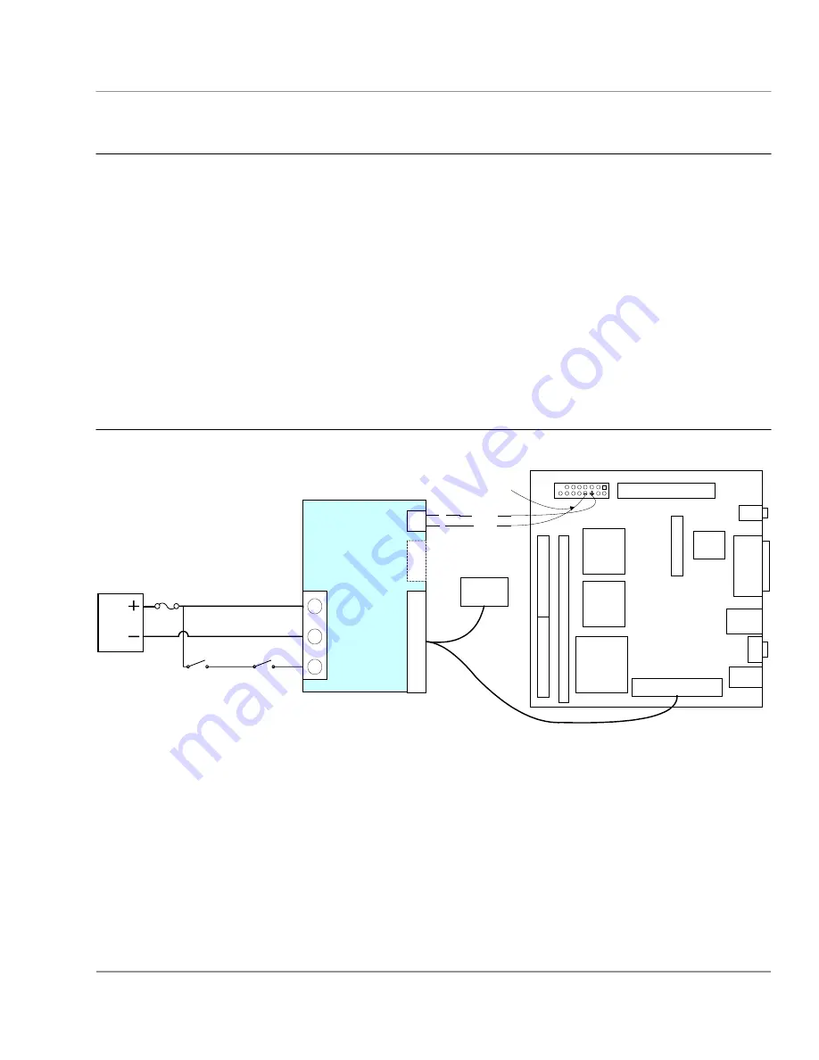
Application Wiring Example 


t

1
2

8

pin

20

Pin

20 Pin

2

3

1

PWR SW

ATX Power

out

+ BATT

GND

IGN

+

-

To Drives

Power

Connector

Front Panel Connector

To ATX soft power

switch pins

ATX Power connector

OPUS Smart DC-

DC Power supply

VIA EPIA-M  Mini-ITX  Main Board

or ATX Compatible mother board

Power input

& IGN Conn.

Fig. 1     OPUS DC-DC Power Supply to VIA EPIA-M  Mini ITX  Mother board Application Drawing

1
2

8  6

Green

White

Battery

Ignition Switch

Fuse

ON/OFF Switch


Summary of Contents for DCX3.1209

Page 1: ...to shut down the PC after a delay of 20 minutes The power supply outputs are monitored to assure proper PC operation Wake up on interrupt is implemented to access the vehicle computer over wireless LA...

Page 2: ...r the this function If the PC is manually put into power down mode to restart the PC the ignition must be turned off for at least 5 sec and turned on again Abnormal condition If the green LED light fl...

Page 3: ...r cable to connect the unit to the battery Use an 18 AWG wire for ignition or on off Note Do not share power cable with other equipment s Make sure the voltage at Input power connector of the DC DC ac...

Page 4: ...eup from suspend Cntrl F1 or whatever is your preference 11 Type Esc to go back to Power Management Setup 12 Type Esc to go back to top level of BIOS setup menu 13 Select Save and Exit setup Type Ente...

Page 5: ...1 Shut down the computer Click Start Shut Down Shut Down under Shut Down Windows Note Some applications do not support standby mode In that case select Power off or hibernate in step 6 above Configuri...

Page 6: ...y for minimum time Default factory setting 4 Install the OPUS DC DC Power Supply in your computer 5 Connect the bottom end of 20 pin ATX power cable Y cable to OPUS DC DC power supply J7 ATX ITX Power...

Page 7: ...ation for Standby mode testing Use the application as you would normally 6 Turn off the computer by turning the ignition switch off The computer should go into Standby or shut down mode as it was set...

Page 8: ...ut Batt GND OPUS DCX3 DC DC LCD Monitor etc OPUS DCLxx DC DC Two Way Radio etc Audio Power Amplifier Remote Trigger output DC DC APM control Relay Not Used Not Used Fig 2 Remote Trigger output and or...

Page 9: ...ers 2 way radio Cameras Remote DVD or CR ROMs etc The output of the remote trigger Red wire can be connected directly to the Audio Power amplifier s Remote or Trigger input In this application the com...

Page 10: ...p below 10 6V 2 Flashes The computer power up sequence failed Reasons 1 Check the wiring of the two wire power switch cable from power supply connector J9 to power switch pins on the ATX motherboard I...

Page 11: ...V 6 A max 8 A pk 50mV p p max 2 5 V 6 A max 8 A pk 50mV p p max 2 12 V 2 5A max 3 A pk 50mV p p max 2 12 V 0 2 A max 4 A pk 150mV p p max 10 5 V standby 1 5 A max 2 A pk 50mV p p max 2 Power supply ef...

Reviews: