


SRO70 Installation Manual
3
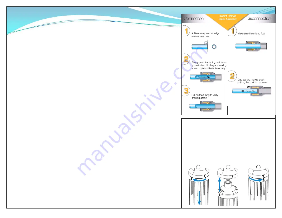
Installing or Replacing QT Cartridges
NOTE: Before installing or replacing QT Cartridges, make
sure to remove the plugs in the QT heads.
1. Close feed water valve.
2. Twist and pull down to remove cartridges.
3. Line up the upward-arrow on the new cartridge with the upward
pointing arrow on the head. Push cartridge up into head until it
stops.
4. Turn to right until it stops. NOTE: labels might not always face
forward.
5. Open feed water valve.
v
Installation Requirements
Operating a system on water supplies outside of the
parameters listed below may lead to premature membrane
failure. This product is for commercial use only and must be
installed and maintained in accordance with manufacturer’s
guidelines and local regulatory plumbing codes.
Operating parameters
Typical Membrane TDS rejection: 97+%
Feed Temperature: 40 - 100° F (4 - 38° C)
Feed pressure: 50 - 80 psi (3.4 - 5.9 bar) at 1 gpm
Production (at 77°F, 60 psi): 70 gals/day (2.9 gals./hr)
Recovery: up to 33%
IMPORTANT NOTE: The production rate is strictly
dependent on feed water temperature and pressure.
For example: Operating pressure of 30 psi will reduce
production by 50%, or 48˚F feedwater will reduce production
by 50%.
Location
The system should be installed indoors, within 25 ft of the
equipment water is being supplied to, and protected from
the elements. Do not let the processor or storage tank
freeze or be exposed to rain or direct sunlight.
Feed water connection
An adequate flow and pressure of water to the unit is
essential for successful operation.
Drain
A drain should be located within 5 ft of the system. Drain
must allow a minimum flow of 2 gals/min. Compliance
with most local plumbing codes requires installation of an
approved air gap in the drain line. The drain connection
should be accessible for system set-up and service.
Feed-water chemistry
Feed TDS: Up to 1200 ppm
Feed pH: 6 - 10
Hardness: 12 grains or less
Free chlorine: <2 mg/l
Iron (Fe): 0.1 mg/l max.
Turbidity: <0.05 NTU
Manganese: 0.05 mg/l max.
Hydrogen sulfide: 0.0 mg/l
Note: The presence of silica or flocculants such as alum or
cationic polymers in the feedwater may cause membrane
fouling and may require special chemical pretreatment or
periodic membrane cleaning. Please note that membrane
failure due to fouling is not covered by the warranty.
Storage Tank
The tank must be located within 10 ft of the water processor.
The floor beneath the storage tank should be smooth, clean
and free of sharp objects that could puncture the bottom of
the tank.
Optimized Water Lines to Equipment
Tubing, piping and associated fittings connecting Optimized
water lines to equipment should be food grade material that
meets NSF Std 51 or 61 with a minimum pressure rating of
75 PSI. Optimized water may react with most metal piping
imparting a bad taste. Plastic pipe or reinforced opaque
beverage tubing are acceptable choices for Optimized water
distribution. The larger inside diameter tubing or hose, the
better to minimize pressure drop.
2
3
4