


6212A Manual Version 14.56.docx
Page 8 of 58
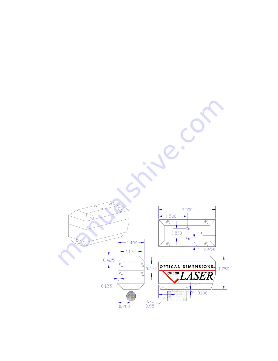
Physical Mounting
The Lasercheck head is supplied with a 1/10-inch thick footplate on the bottom. This will align the head within
specification on flat surfaces. If surfaces are cylindrical, then optional alignment feet should be used. For
surfaces with different geometry, alignment fixturing should be used. An understanding of alignment principals
of Lasercheck is required for development of fixturing. Please read the section “LASERCHECK ALIGNMENT
PRINCIPALS AND PRECEDURES” later in this manual to understand principals of alignment.
When performing measurements, set the long axis of the head perpendicular to the dominant “lay” of the
surface that you wish to measure. The long axis of the head determines the direction of measurement in the
same way that the direction of motion of a stylus on a stylus gage determines the direction of measurement.
Mounting/Fixturing Lasercheck
There are drilled and tapped holes on the Lasercheck sensor head that can be used for mounting and installing
Lasercheck in an automated inspection application. The head should be positioned at a location where surface
will be at the correct vertical and horizontal position relative to the gage head (see appendix section on
Lasercheck Alignment Principles and Procedures). The surface can move under the gage or the gage can move
over the surface. In either case, alignment must be maintained during relative motion. An air knife can be used
prior to the gage to clean coolant etc. from surfaces to be inspected if necessary. A “Start” sensor or input
should be positioned to be activated when the gage or surface is positioned to measure at the beginning of the
surface or process. A “Stop” sensor or input should be positioned to be activated when the gage or surface is
positioned to measure at the end of the surface or process. Both of these sensors should be wired to the “Input”
connector on the back of the control box as described in the Appendix – Input and Output Pinouts section.