background image

10 


4.  Feed the 5-core wire from the Adapter through the entire drag chain. Feed the wire all the way to the 

Mounting Plate / Holder on the spindle mount. 

○  Make sure that there is enough wire when the Z-Axis is lowered all the way. 


5.  Close the cable drag chain on the X-Carve. 
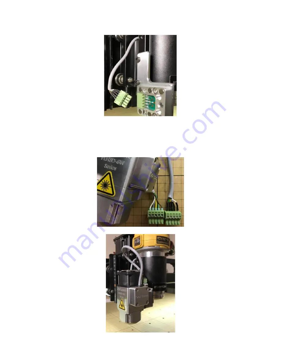
6.  Insure that the pinout for the Docking Station connector is correct on the 

○  Laser Module 
○  Adapter Mounting Plate (on spindle mount) 

NOTE: The pinout for the Adapter Mounting Plate / Holder Docking Station should mirror the 
Laser Modules pinout. 


7. 

Attach the laser module to the spindle mount.


Summary of Contents for PLH3D 6W-XF

Page 1: ......

Page 2: ...iguration 16 Device Setup 16 5 Usage and Operation Software and Hardware 20 Basic Safety Guidelines 20 Basic Operation Guidelines 20 Common Cutting Parameters 20 6 LightBurn Basic Usage 21 Laser Opera...

Page 3: ...e element lens though it causes a bigger optical power loss allows you to obtain a smaller beam spot This helps to obtain a higher power density to area ratio while also giving the added benefit of a...

Page 4: ...luded Parts PLH3D 6W XF Engraving Laser Head PLH3D 6W LaserDock Docking Station PLH3D Series Adapter for X Carve Machine PLH3D 6W Nozzle 43mm Spindle Adapter 450nm Laser Safety Goggles PLH3D Lens Regu...

Page 5: ...4 X Carve Mount for PLH3D Series Collimator 400 700nm 12V 3 5A power supply Includes adapters for wall plugs...

Page 6: ...ken Do not engrave or cut any kind of material that contains vinyl or material with a similar chemical composition Such material is corrosive and deadly dangerous Before making any adjustments changin...

Page 7: ...er power density or medium to long working distance 3 The High Efficiency Lens is an aspheric lens f 4 mm This lens is recommended for applications requiring a higher power when it is practical to use...

Page 8: ...der There are two primary ways to install the Mounting Plate to the Spindle Holder and one less conventional way that is compatible with the Inventables X Carve Dust Collection System Mounting Option...

Page 9: ...8 Install Docking Station onto Laser Module Be sure to check screws length when installing 3 Test Mounting The docking station should snap into place with the magnets...

Page 10: ...the zip ties 2 Connect the 2 core wire Adapter inputs to the spindle outputs on your X Controller Connect the Brown wire to Spindle PWM Connect the White wire to GND 3 Open the cable drag chain on th...

Page 11: ...gh wire when the Z Axis is lowered all the way 5 Close the cable drag chain on the X Carve 6 Insure that the pinout for the Docking Station connector is correct on the Laser Module Adapter Mounting Pl...

Page 12: ...pter is Off Connect Power Supply to the Adapter 10 Turn on your Adapter the switch should glow red and the fans on the laser module should spin up 11 Done ready to engrave NOTE The laser should NOT pr...

Page 13: ...lasses Goggles on for this step 1 Scroll to Console 2 Paste 32 0 and press enter Insure that Laser Mode is Disabled 3 Paste M3 S1 and press enter THIS WILL FIRE THE LASER a Laser should fire at its lo...

Page 14: ...on millimeters 12 0 002 Arc tolerance millimeters 13 0 Report in inches Boolean 20 1 Soft limits enable Boolean 21 1 Hard limits enable Boolean 22 1 Homing cycle enable Boolean 23 3 Homing direction i...

Page 15: ...TE If you are not able to click the Upload Firmware option make sure that 1 Easel Drivers are Installed 2 Make sure your machine is connected to your USB port 3 Stop any programs that also are automat...

Page 16: ...still having issues getting your machine to behave as expected go through the X Carve Machine Setup Configure Note PWM Min Max 1 Scroll down to Console 2 Paste in the following settings one at a time...

Page 17: ...ou are not limit to just this software for generating your G Code and sending it to your CNC Machine See the Advanced Users section of this manual once you are confident and feeling adventurous Device...

Page 18: ...is is the max travel in the X axis and Y axis You Can look up your X Carves max travel here at Inventables Support 1000mm X Carve X Axis 770mm Y Axis 780mm 750mm X Carve X Axis 550mm Y Axis 550mm 500m...

Page 19: ...ative Z moves only Fast Whitespace Scan 8000 mm min Enable Laser Fire Button GRBL v0 9j and older if GRBL setting 30 Maximum spindle speed RPM can t be altered G Value Max GRBL v0 9j and older does no...

Page 20: ...19...

Page 21: ...eters Use these setting to help determine settings to use when cutting can also help when engraving Note that these parameters can differ between materials cooling temperature of laser module focus di...

Page 22: ...ize the outline of the part before moving on to the next operation Image Types There are two primary image types that you can work with Vector and Raster These image types present different ways of en...

Page 23: ...We will start with some basic shapes 2 Select different Layers from the bottom layers bar and apply a different layer to each vector 3 As different layers are applied you will see the applied layers...

Page 24: ...head Laser will move to its home position 7 Select the Move widget this button can usually be found at the bottom of the Cuts widget 8 Move your toolhead laser to it work position where you would lik...

Page 25: ...0 P1 X0 Y0 Z0 b Goto Work Position X Y G54 G0 X0 Y0 c Goto Work Position Z G54 G0 Z0 d Enable Laser Mode 32 1 e Disable Laser Mode 32 0 10 Press Zero Work Position macro you created to set the startin...

Page 26: ...ld glow red and the fans on the laser module should spin up 1 13 Start Engraving a In the Laser widget 1 Insure that Start From is set to Absolute Coords 2 Trace Frame the engraving on the work area b...

Page 27: ...EXPRESS OR IMPLIED INCLUDING BUT NOT LIMITED TO THE WARRANTIES OF MERCHANTABILITY FITNESS FOR A PARTICULAR PURPOSE AND NON INFRINGEMENT IN NO EVENT SHALL THE AUTHORS OR COPYRIGHT HOLDERS BE LIABLE FO...

Page 28: ...ded that you backup export your settings This can be done by sending GRBL the command the view grbl settings command NOTE you can export your settings using Arduino IDE or Easel Connect your computer...

Page 29: ...s on the GNEA GRBL Wiki Compiling Grbl Download the latest GRBL source release Source code zip this contains the GRBL library Extract the grbl x x YYYYMMDD zip Open and edit the config h file found th...

Page 30: ...1 9 15 mac x64 dmg and many more 2 Install CNCjs by double clicking on the downloaded installer Software Usage 1 Launch CNCjs from your Start Menu Application Dock 2 In the Connection widget Select th...

Page 31: ...eyboard input can be enabled by clicking the keyboard icon at the top of the widget 6 Set Laser Height to 60mm above work area Use a ruler and measure 60mm above from just below the head of the laser...

Page 32: ...a brief moment Hooray 11 Load G Code You can drag and drop G Code into the CNCjs window to load it A preview of the g code should appear 12 Run G Code Click the play button at the top to run the G Cod...

Page 33: ...are two primary image types that you can work with Vector and Raster These image types present different ways of engraving each with their own benefits Choose Create your design and export it as a DF...

Page 34: ...hickness Used to determine passes needed when cutting through material Curve Accuracy Value determines steps in curve Lower number smoother curve Leave at default One Pass Thickness Material cut per p...

Page 35: ...t the size of a pixel Used to help scale the image Example 1 pixel 0 1 mm 10 pixels will fit in 1 mm scan line X and Y Resolution Used to specify the source image resolution Keep Aspect Ratio Keeps th...

Reviews:

Related manuals for PLH3D 6W-XF