No.16S058-01
8/49
STC-HD133 Series (STC-HD133DV / STC-HD133SDI) /
STC-HD93 Series (STC-HD93DV / STC-HD93SDI) Users guide
3.2.2.
The camera setting by SM06B-SRSS-TB (JST) connector on the board type camera
A. It is necessary to assign the function for each button by the communication software.
Please check the default functions at “E. The remote controller function”.
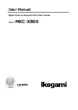
B. The connector for the remote controller
Note: The connector location for SDI model is same.
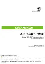
C. The remote controller circuit diagram
1
2
1
2
1
2
1
2
1
2
1
2
1
2
1
2
1
2
1
2
3
4
5
6
SW11
SW21
SW12
SW13
SW22
SW23
SW31
SW32
SW33
ROW2
ROW3
ROW1
COLUMN2
COLUMN3
COLUMN1
D11
D21
D31
D12
D22
D32
D13
D23
D33
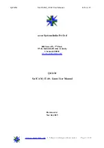
D. The example remote controller
The function for the remote controller buttons
The below functions are assigned for SW-11 to SW-13.
SW-11: Page (-)
SW-13: Page (+)
Any function dose not assign for the SW-12, SW-21 to SW-33.
Please assign the function by the communication software if it is necessary.
SW-11
SW-13
SW-12
SW-21
SW-23
SW-22
SW-31
SW-33
SW-32