No.14S056-11
33
STC-CMC120APCL, STC-CMB120APCL
Specifications and Users guide
5.2
Pulse width trigger mode
In this trigger mode with positive polarity, the camera exposure starts at the rising edge of the trigger pulse and stops
at the falling edge of the trigger pulse. Therefore, In the case of the exposure positive polarity is selected, the
exposure periods are the high states of the trigger pulse.
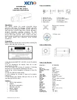
5.2.1 Pulse width trigger mode
Note.1: The exposure time sets by the pulse width of the trigger signal. No FVAL output without any trigger signal.
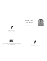
5.2.2 Pulse Width Trigger mode (Exposure timing)
Note.1: The trigger signal is removed by the filtering if the pulse width of the input trigger signal is less than 1.5us.
Please input the trigger signal has more than 1.5 us pulse width.
Note.2:
α
1(Exposure time offset) is.
10,8,4,2TAP
41[us] (Edge Preset and Variable at Line unit)
42[us] (Pulse Width and Variable at us unit)
3TAP
42[us] (Edge Preset and Variable at Line unit)
43[us] (Pulse Width and Variable at us unit)
Trigger signal
Exposure time
Exposure time: T1' = T1 + α
1 *Note2
T1
1.5us
Filtering *Note.1
T1'
Exposure
time
Internal VD
exposure
Trigger signal
(Positive
)
Video out
*Note. 1
FVAL
For more information please contact Aegis Electronic Group, Inc. *(888)687-6877 *[email protected] *http://www.aegiselect.com
Aegis
Electronic
Group,
Inc.