background image

Advanced UsageAdvanced Usage

Ct

i

it

h

Connecti

n

g w

ith 

CPIE PLC

Designing Screens

Preparation

NV-series PT
Simple Operation 
Handbook

- A case of connection to a CP1E PLC -

Table of Contents

Preparation

Required Devices 

               

2

Wiring and Connection 

          

4

Turning on the Power 

           

6

Displaying the NV System Menu 

  

7

Setting the CPIE Serial Port 

      

8

Designing Screens

Creating New Screen Data 

      

12

Setting the NV Communications 

 

15

Creating Switch Parts 

          

16

Creating Lamp Parts 

           

19

Creating Data Parts 

            

21

Creating Keyboard Screens 

     

23

Creating Character Stings

       

26

Connecting with CP1E PLC

Transferring Screen Data 

       

28

Checking Operation 

            

31

Advanced Usage

Switching Screens from CP1E

   

32

Changing Backlight Colors 

from CP1E 

                    

34

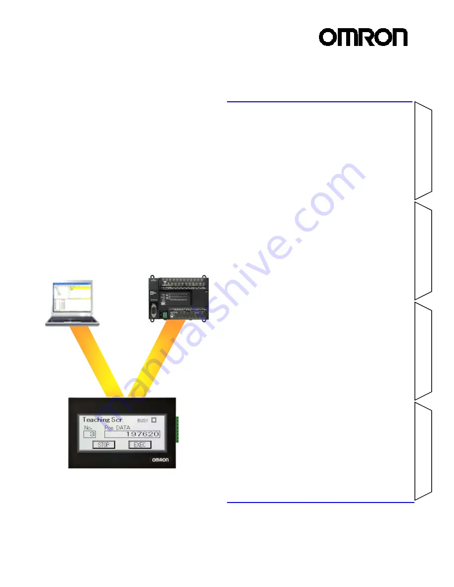
Connecting PC and PLC via NV 

  

35

The NV3W-V1 is added.

Summary of Contents for NV3Q-MR21

Page 1: ...the NV System Menu 7 Setting the CPIE Serial Port 8 Designing Screens Creating New Screen Data 12 Setting the NV Communications 15 Creating Switch Parts 16 Creating Lamp Parts 19 Creating Data Parts...

Page 2: ...40 V1 NV3W MG40 V1 QVGA Models NV3Q 3 6 inch Package PLCs with Exceptional Cost CP1E Three color LED backlight of white pink and red NV3W MRxx x V1 Three color LED backlight of green orange and red NV...

Page 3: ...ramming software for PLC Included in a package of CX One Lite Ver 4 Micro PLC Edition CX Programmer Ver 9 Included in a package of CX One Ver 4 CX Programmer Ver 9 Select from two types of software NV...

Page 4: ...C 5 V power green Name color RD orange SD blue SG pink NV3W V1 5 VDC The NV3W V1 5 VDC type does not need a power supply unit The 5 V power is supplied from the PLC through the XW2Z 200T 4 Special Cab...

Page 5: ...only When the CP1E uses a 24 VDC power supply Wire the 24 VDC power supply as shown below XW2Z 200T 3 2 m without 5 V Line XW2Z 500T 3 5 m without 5 V Line When the NV3W V1 24 VDC type the NV4W or the...

Page 6: ...w Normal operation default Prohibiting moving to System Menu F ROM clear Note 1 The data saved in the F ROM includes screen data and NV configuration data Note 2 Other than the DIP switch setting you...

Page 7: ...order Note Touch the points A B and C one at a time in order Do not press these points at the same time 2 The startup screen of the System Menu will be displayed The startup screen of the System Menu...

Page 8: ...bit 1 Parity bit Even Communications setting for the RS 232C serial port built in the CP1E Use the PLC programming tool CX Programmer Follow the steps below to set the RS 232C serial port built in the...

Page 9: ...m the Windows Start Menu to start the CX Programmer 2 Select PLC Auto Online Direct Online from the menu bar 3 In the Direct Online Dialog Box select USB connection for the PC PLC CP1E connection type...

Page 10: ...ar 1 Confirm that stopping the ladder program do not cause any problem Click the Yes Button 2 The CP1E operation mode changes to the Program Mode Stopped is displayed Program Mode is displayed Transfe...

Page 11: ...appears Select Options Transfer from PLC from the menu bar The second value from the left of Format is the stop bit Be sure to set it to 1 when the PLC is connected to an NV Click Click 3 The PLC sett...

Page 12: ...signer from the Windows Start Menu 3 On the Select Model Dialog Box select the NV model and the NV type and enter the project name Click the Next Button NV Model Select the PT model 2 When the NV Desi...

Page 13: ...and write data in bit units such as Backlight Light Blink In total six words are allocated The system memory is used for the PLC to control the basic operations such as switching screens The specifie...

Page 14: ...Base Screen Parts Library A parts library contains parts such as switches lamps data displays and keyboards Your own parts library can be created by registering customized parts to reuse them Screen...

Page 15: ...E communications was set as follows Set the same for the NV communications Mode Host Link Baud rate 115 200 bps Data length 7 Stop bit 1 Parity bit Even The stop bit for the NV serial communications i...

Page 16: ...creating a switch part CIO 10 00 in the PLC is turned ON when the switch is pressed and turned OFF when it is released Momentary operation Normally the OFF label is displayed While the switch is press...

Page 17: ...the bit address in the PLC ON OFF Indication Select either On to switch the ON OFF indication or Off not to switch it When you select On set also the switch timing Creating the switch labels 1 Select...

Page 18: ...After setting click the OK Button to close the setting dialog box This completes creating a switch part 1 Change the character color to white Confirming the part ON OFF state by preview Select the par...

Page 19: ...LC turns ON and OFF Example of creating a lamp part The lamp changes color depending on the ON OFF state of CIO 10 00 in the PLC The lamp is white when CIO10 00 is OFF It turns black when CIO10 00 is...

Page 20: ...for the lamp part Double click the lamp part Select the Basic Setup Tab Set the ON OFF Bit Field Click the OK Button to close the dialog box This completes creation of the lamp part ON OFF Bit Set the...

Page 21: ...s from the keyboard screen as well Example of creating a data part This data part indicates the value of D100 in the PLC in a decimal number The keyboard screen appears by touching the part Enter a va...

Page 22: ...ck the Input Tab Select On Make the input settings Click the OK Button to lose the setting dialog box This completes the data part setting Supported Keyboard Specify the keyboard input method Keyboard...

Page 23: ...art Creating a keyboard screen 1 Select File Keyboard Screen from the menu bar Click 2 The Edit Keyboard Screen Dialog Box will be displayed Click 0 and then click the Draw Button to open the keyboard...

Page 24: ...ct the Basic Setup Tab Make a necessary setting as shown below Note This example uses the default setting Click the OK Button to close the dialog box Image The setting can be checked here Clicking a k...

Page 25: ...drop it at any desired space on the keyboard screen 1 Use the Parts Library Standard NV3W V1 3 Use the part Data Drag and drop 2 Click the Parts Group Selection Button and then select Data Setting the...

Page 26: ...this example the character string Value is outlined Creating a character string 1 Click the Character String Button on the graphic bar 2 Click the position on the base screen where you want to input...

Page 27: ...image to show on the NV and copy it 3 On the NV Designer open the screen to paste the image Right click on the screen and select Paste from the context menu Alternatively press Ctrl V to paste the im...

Page 28: ...the transfer method 1 Select PT Transfer Transfer from the menu bar Click 2 Select USB in the Communication Method Field Click the OK Button to close the Transfer Data Dialog Box 1 Communication Metho...

Page 29: ...ferring The Transfer Data Dialog Box closes Click Use the shortcut Ctrl T Transfer is a frequently used operation Use the shortcut for your convenience Transfer Data After Clear NV Screen When this ch...

Page 30: ...s the Watch Window to monitor and change the contents of PLC addresses from the CX Programmer Opening the Watch Window Select View Window Watch from the menu bar Double click Enter an address Enter a...

Page 31: ...oes off Checking operation of the data part and keyboard When you touch the data part the keyboard screen appears You can enter a value The screen changes to the keyboard screen Enter a numerical valu...

Page 32: ...base screen to an existing project The screen is used to confirm the screen switching operation 1 Start the NV Designer and open a project Double click 1 in the Screen Manager Base screen 1 will open...

Page 33: ...e N 2 Current screen number NV PLC Word Area Screen number from PLC This word contains the number in binary of the screen specified by the PLC for the NV to display Current screen number This word con...

Page 34: ...0 13 on the CX Programmer to change the backlight status Set the bits for the backlight color and backlight light blink and then turn ON the Backlight Control Enable Bit This is the example of NV3W MG...

Page 35: ...NV PC NV3W V1 NV4W NV3Q Host Link SYSMAC CS CJ CP Series PC connection cable Setting 1 On the CX Programmer open a project of a CS CJ or CP series PLC Double click the PLC in the project tree The Cha...

Page 36: ...2015 0715 0110 V411 E1 02...

Reviews: