Unit Components and Specifications
SECTION 2
2.
Input indicators (yellow)
The input indicators are lit when the corresponding input terminal is ON. The
status of an input indicator will reflect the status of the input even when that
input is being used for a high-speed counter.
Note
a)
When interrupt inputs are used in interrupt input mode, the indicator
may not light even when the interrupt condition is met if the input is
not ON long enough.
b)
Input indicators will reflect the status of the corresponding inputs
even when the PLC is stopped, but the corresponding input bits will
not be refreshed.
3.
Output indicators (yellow)
The output indicators are lit when the corresponding output terminal is ON.
The indicators are lit during I/O refreshing. The status of an output indicator
will also reflect the status of the corresponding output when the output is be-
ing used as a pulse output.
4. PLC
status
indicators
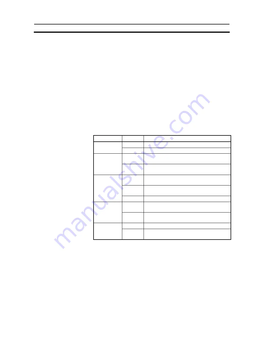
The following indicators show the operating status of the PLC.
Indicator Status
Meaning
ON
Power is being supplied to the unit
PWR
(green)
OFF
Power isn’t being supplied to the unit
ON
The PLC is operating in RUN or MONITOR
mode
RUN
(green)
OFF
The PLC is in PROGRAM mode or a fatal
error has occurred.
ON
A fatal error has occurred. (PLC operation
stops.)
Flashing
A non-fatal error has occurred. (PLC
operation continues.)
ERR/ALM
(red)
OFF
Indicates normal operation.
Flashing
Data is being transferred via the peripheral or
RS-422/485 port.
COMM1
(yellow)
OFF
Data isn’t being transferred via communica-
tions port.
Flashing
Data is being transferred via the RS-232C port
COMM2
(yellow)
OFF
Data isn’t being transferred via communica-
tions port.
5. Communications
port
Connects the PLC to a Programming Device (including Programming Con-
soles), host computer, or standard external device. Use a proper Connecting
Cable (CPM2C-CN111, CS1W-CN114, CS1W-CN118, or CS1W-CN226).
Note
a)
A CQM1H-PRO01-E Programming Console can be connected di-
rectly to the PLC.
b)
A C200H-PRO27-E Programming Console can be connected di-
rectly to the PLC with a CS1W-CN224/CN624 Connecting Cable.
c)
Use a CPM2C-CN111 or CS1W-CN114 Connecting Cable to con-
nect to the communications port as a peripheral port. The communi-
cations port can be used simultaneously as both a peripheral port
and RS-232C port by using the CPM2C-CN111 Connecting Cable.
d)
Use a CPM2C-CN111, CS1W-CN118 or CS1W-CN226 Connecting
Cable to connect to the communications port as a RS-232C port.
27
Summary of Contents for 3G3MV-P10CDT-E
Page 2: ...3G3MV P10CDT PLC Option Unit User s Manual Revised June 2003 ...
Page 38: ...Unit Components and Specifications SECTION 2 2 1 4 Dimensions 68 128 55 25 ...
Page 43: ......
Page 85: ...Example Programs Appendix B 72 ...
Page 86: ...Example Programs Appendix B 73 ...
Page 87: ...Example Programs Appendix B 74 ...
Page 88: ...Example Programs Appendix B 75 ...
Page 90: ...Example Programs Appendix B 77 ...
Page 91: ...Example Programs Appendix B 78 ...
Page 97: ...Example Programs Appendix B B 4 9 Programs User_Parameter_Init 84 ...
Page 98: ...Example Programs Appendix B 85 ...
Page 99: ...Example Programs Appendix B User_Application Pos_Loop 86 ...
Page 100: ...Example Programs Appendix B 87 ...
Page 101: ...Example Programs Appendix B 88 ...
Page 102: ...Example Programs Appendix B 89 ...
Page 103: ...Example Programs Appendix B 90 ...
Page 104: ...Example Programs Appendix B 91 ...
Page 105: ...Example Programs Appendix B 92 ...
Page 106: ...Example Programs Appendix B 93 ...
Page 107: ...Example Programs Appendix B Pos_Home_Sequence 94 ...
Page 108: ...Example Programs Appendix B 95 ...
Page 109: ...Example Programs Appendix B 96 ...


