


Specifications
Model
Control
mode
Input speci-
fications
Maximum
response
frequency
Output
specifica-
tions
3G3FV-
PPGA2
V/f with PG
feedback
mode
Single pulse
input
Open
collector
output
compatible
30 kHz (50%
duty)
Pulse monitor
output
Voltage
output
12 VDC
(
±
10%),
20 mA max.
3G3FV-
PPGB2
Flux vector
control mode
A/B-phase
pulse input
Open
collector
output
compatible
30 kHz (50%
duty)
A/B phase
pulse monitor
output
Open
collector
output
24 VDC max.
30 mA max.
3G3FV-
PPGD2
V/f with PG
feedback
mode
Single pulse
input
RS-422 level
input
300 kHz
(50% duty)
Pulse monitor
output
RS-422 level
output
3G3FV-
PPGX2
Flux vector
control mode
A/B/Z-phase
pulse input
RS-422 level
input
300 kHz
(50% duty)
A/B/Z-phase
pulse monitor
output
RS-422 level
output
Note
Inverter speed control accuracy falls off at frequency bands
below 50 Hz.
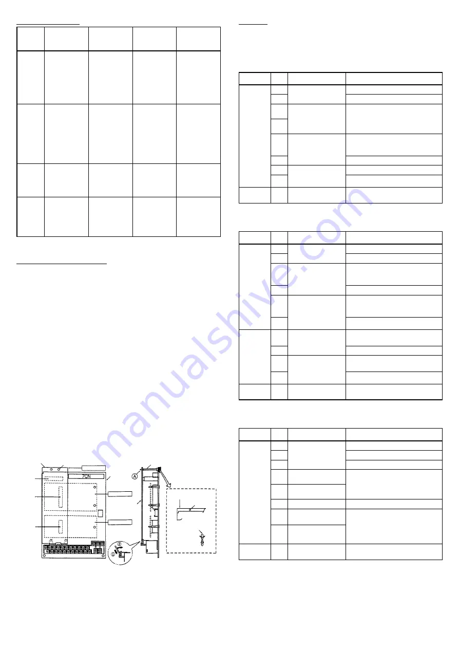
Mounting Procedure
1, 2, 3... 1. Be sure to turn OFF the main Inverter power supply,
wait at least 1 minute (at least 3 minutes for 30-kW-or-
higher Inverters), remove the front cover of the Inverter,
and make sure the charge indicator is not lit.
2. The PG Speed Control Card is an option A. Mount the
Card in the option-A location as shown in the diagram
below.
3. Insert the spacer that is provided into the spacer mount-
ing hole located on the mounting base of the Inverter.
There are 2 holes located on 3.7-kW-or-lower Inverters.
Insert the spacer in the hole on the 7CN side. Be very
careful because spacers cannot be removed if they are
inserted in the wrong hole.
4. Proceed in order with steps
A
and
B
in the enlarged
view below. Align the PG Speed Control Card and the
supports, make sure the connector on the Card is
aligned with the option-A connector, and then push the
spacer through the spacer mounting hole on the Card.
(Side View
a
)
Make sure the 4CN positions are properly aligned, and
push the spacer through the hole until it clicks into
place.
5. Connect the ground wire of the Card to the FG terminal
12(E) on the Inverter control circuit board.
Front View
Side View
PG Speed
Control Card Spacer mounting hole
4CN
option-A
connector
2CN
option-C
connector
3CN
option-D
connector
Option A
Control
circuit
board
Option C
Option D
Option-A mounting spacer
(Accessory: SRNT41028-9)
Inverter
mounting base
PG Speed
Control Card
Inverter
mounting base
Spacer mounting
hole
Control
circuit board
Spacer
Mounting
base side
Option A side
Spacer mounting
Enlarged View
Wiring
Description of PG Speed Control Card Terminal Blocks
•
3G3FV-PPGA2 (For V/f With PG Feedback Mode Only)
Terminal
No.
Description
Specification
TA1
1
Pulse generator
12 VDC (
±
5%), 200 mA max.
2
power supply
0 VDC (Power supply ground)
3
+12-V/open
collector switching
This terminal switches between
12-V voltage input and open
4
collector switching
12-V voltage input and open
collector input. Short pins 3 and
4 for open collector input.
5
Pulse input
H: +4 to 12 V,
L: +1 V max. (30-kHz maximum
response frequency)
6
Pulse input common
7
Pulse monitor
12 VDC (
±
10%), 20 mA max.
8
output
Pulse monitor output common
TA2
(E)
Shielded wire
connection
---
•
3G3FV-PPGB2 (For Flux Vector Control Mode Only)
Terminal
No.
Description
Specification
TA1
1
Pulse generator
12 VDC (
±
5%), 200 mA max.
2
power supply
0 VDC (Power supply ground)
3
A-phase pulse
input
H: +8 to 12 V,
L: +1 V max. (30 kHz maximum
response frequency)
4
Pulse input common
5
B-phase pulse
input
H: +8 to 12 V,
L: +1 V max. (30 kHz maximum
response frequency)
6
Pulse input common
TA2
1
A-phase monitor
output
Open collector output: 24 VDC
max., 30 mA max.
2
A-phase monitor output common
3
B-phase monitor
output
Open collector output: 24 VDC
max., 30 mA max.
4
B-phase monitor output common
TA2
(E)
Shielded-wire
connection
---
•
3G3FV-PPGD2 (For V/f With PG Feedback Mode Only)
Terminal
No.
Description
Specification
TA1
1
Pulse generator
12 VDC (
±
5%), 200 mA max.
2
power supply
0 VDC (Power supply ground)
3
5 VDC (
±
5%), 200 mA max.
4
Pulse input +
Line driver input (RS-422 level
input)
5
Pulse input –
input)
300-kHz maximum response
frequency
6
Common
---
7
Pulse monitor
Line driver output (RS-422 level
output)
8
Pulse monitor
output –
TA2
(E)
Shielded-wire
connection
---
Note
5 VDC and 12 VDC cannot be used simultaneously.


