


•
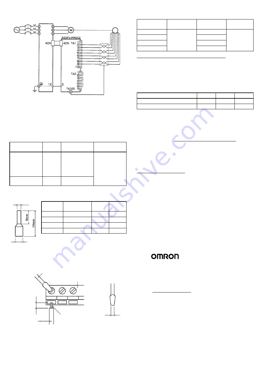
3G3FV-PPGX2 (For Flux Vector Control Mode Only)
3-phase,
200 VAC
(400 V)
SYSDRIVE
3G3FV
0-V power supply
5-V power supply
A-phase pulse output –
E6B2-CWZ1X
Encoder
B-phase pulse output –
A-phase pulse
monitor output
B-phase pulse
monitor output
A-phase pulse
B-phase pulse
Z-phase pulse output –
Z-phase pulse
Z-phase pulse
monitor output
L1 (R)
L2 (S)
L3 (T)
T1 (U)
T2 (V)
T3 (W)
Note
1. Be sure to use twisted-pair shielded wire for the signal
line.
2. Do not use the PG power supply for equipment other
than the PG (encoder). Otherwise, noise may cause
faulty operation.
3. Make sure that PG wiring is less than 50 m long.
4. Make sure the signal line is placed at least 30 cm away
from the Inverter output line and other power lines.
Wire Thicknesses
Terminal
Terminal
screw
Wire thickness
(mm
2
)
Type of wire
Pulse generator
power supply
Pulse input
Pulse monitor
output
---
Stranded wire:
0.5 to 1.25
Single wire:
0.5 to 1.25
Shielded
twisted-pair wire
Shielded,
polyethylene-cove
red vinyl sheath
Shielded line
connection
M3.5
0.5 to 2
cable used for
measuring
Solderless Terminal Sizes (For Signal Line Connection)
For better reliability and easier wiring, we recommend using solder-
less terminals for input and output signals.
Wire
thickness
Model
d2
d2
0.5 mm
2
AI 0.5-8 WH
1.00
2.60
0.75 mm
2
AI 0.75-8 GY
1.20
2.80
1 mm
2
AI 1-8 RD
1.40
3.00
1.5 mm
2
AI 1.5-8 BK
1.70
3.50
(Manufacturer: Phoenix Contact)
•
Wiring Procedure
1, 2, 3... 1. Use a thin-slotted screwdriver to loosen the terminal
screws.
2. Insert the wire from underneath the terminal block.
3. Tighten the terminal screws firmly.
Thin-slotted screwdriver
Control circuit
terminal block
Blade of
screwdriver
Strip the end for
7 mm if no sold-
erless terminal is
used.
Wire
3.5 mm
max.
Blade thickness
0.6 mm max.
Do not solder.
Round Solderless Terminal Sizes and Screw Torque
(Shielded Wire Connection Terminal)
Wire thickness
(mm
2
)
Terminal screw
Size
Screw torque
(N
S
m)
0.5
M3.5
1.25-3.5
0.8
0.75
1.25-3.5
1.25
1.25-3.5
2
2-3.5
Selecting the Number of PG Pulses
3G3FV-PPGA2/PPGB2
The maximum response frequency is 30 kHz.
Select a smaller number of pulses than those given below if neces-
sary based on the encoder pulse width deviation (90
±
45
°
phase dif-
ference) and waveform distortion that occurs with longer cables.
(With an open collector I/O, longer cables increase waveform distor-
tion and make higher frequency pulses difficult to read.)
Maximum motor speed (r/min)
1,800
1,500
900
Encoder pulse count [p/r]
500
600
1,00
Maximum encoder frequency [kHz]
15
15
15
3G3FV-PPGD2/PPGX2
The maximum response frequency is 300 kHz.
The number of encoder pulses (upper limit) can, depending on the
encoder pulse width deviation (90
±
45
°
phase difference), be calcu-
lated using the equation given below.
No. of encoder
pulse [p/r]
60 x max. response freq. (300 kHz)
2 x max. motor speed (r/min)
=
We recommend an encoder of 1,000 to 2,000 [p/r] if the maximum
motor speed is less than 4,000 r/min. Selecting an encoder with a
higher resolution than required will not improve the speed control
range or precision.
Parameter Settings
Control Method Selection: A1-02
When selecting the control method (A1-02), use the control method
setting for the particular Optional Card.
Set “1” (V/f With PG Feedback Mode) for the 3G3FV-
PPGA2/PPGD2 and “3” (Flux Vector Control Mode) for the 3G3FV-
PPGB2/PPGX2.
PG Speed Control Card: F1-01 to F1-13
Use the PG Speed Control Card settings for the application.
A more detailed description of the settings is given in Chapter 5 Basic
Operation of the SYSDRIVE 3G3FV User’s Manual (I516).
Check your settings by referring back to 5-4 Flux Vector Control and
5-5 V/f Control with PG.
d1 dia.
d2 dia.
OMRON Corporation
Systems Components Division
14F Nissei Bldg.
1-6-3, Osaki, Shinagawa-ku,
Tokyo 141 Japan
Tel: (03)3779-9038/Fax: (03)3779-9041
Regional Headquarters
OMRON EUROPE B.V.
Wegalaan 67-69, NL-2132 JD Hoofddorp
The Netherlands
Tel: (31)2356-81-300/Fax: (31)2356-81-388
OMRON ELECTRONICS, INC.
1 East Commerce Drive, Schaumburg, IL 60173
U.S.A.
Tel: (847)843-7900/Fax: (847)843-8568
OMRON ASIAPACIFIC PTE. LTD.
510 Thomson Road #13-03
SLF Bldg.
1129 Singapore
Tel: (65)353-2611/Fax: (65)353-5391
Note: Specifications subject to change without notice.
Printed in Japan
Cat. No. I518-E1-1


