


zipldr_setup&operations
www.OmniTurn.com
(541) 332-7004
(541)-332-1018 fax
Fast... Precise... A
ff
ordable...
Zip Loader Setup & Operations
Omni
Turn
Page 22 of 44
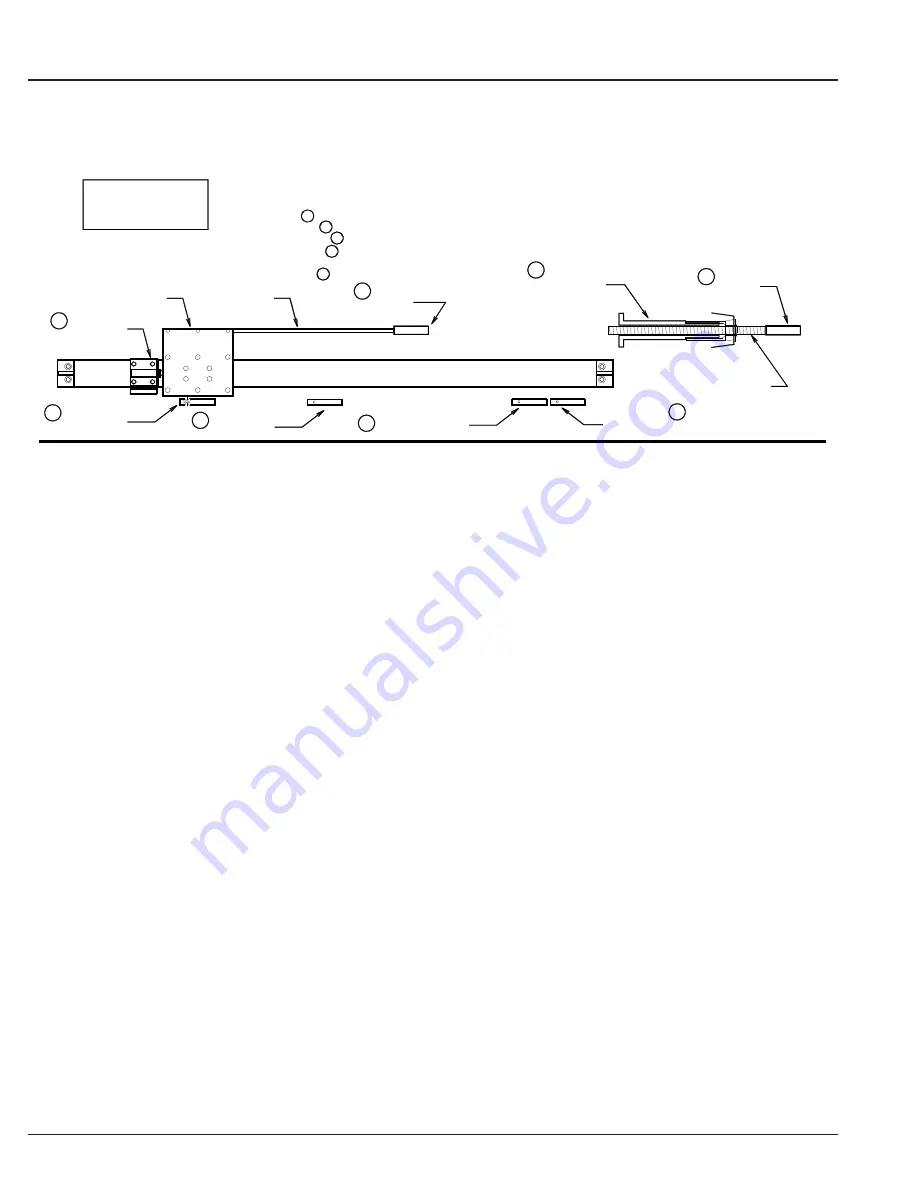
Bar in Collet
Rodless Cylinder
Home Stop
Push-rod
EoB
End of Bar sensor
Spindle Liner
2
5
6
1
Bar Stop
SET-UP
Home sensor
4
Shuttle
Put bar in collet at correct length.
Set bar stop at face.
Set Slow sensor to light just before bar stop with full bar.
Locate Home Stop to just clear bar in vee
Set Home sensor to light when shuttle
is at Home stop.
ZipLoader
BAR MODE
Eject
Home
Slow
Pusher
7
Slow sensor
Set EoB sensor for minimum remnant.
(slightly larger than bar)
(same size as bar)
3
Eject sensor
8
1
7
5
4
6
Bar Mode (M50)
Component Parts and Setup
Refer to the illustration above.
1.
Bar Stop (1):
This is a hard stop mounted at a tool position on the tooling plate (table) of the Om-
niTurn. This stop must be located near the collet then pulled back as the bar feeds so the conditional
sub-routine M97 can check for End of Bar sensor (next page, #7).
2.
Spindle Liner (2):
The liner should be .020 - .040 larger than the bar to insure vibration-free opera-
tion and reliable feeding.
3.
Pusher (3):
The pusher should be about the same size as the bar. The Pusher rides on the ‘vee’ of
the Loader and guides the bar into the liner. It is pressed onto the push-rod and held by a barb.
4.
Home Stop (4):
The Home Stop is clamped to the Rodless Cylinder with cap-screws. It mounts a
shock absorber that the shuttle contacts when at “home”. For most bar work, the Home Stop will be
set almost to the far left end of the Rodless Cylinder. It should be set so that the Pusher just clears the
end of the bar when at Home.
5. Home Sensor (5):
The Home Sensor must light when the shuttle is at the Home Stop with the shock
absorber compressed. The sensor is held in place with a tiny screw. Do not over-tighten the screw as
this may damage the sensor.
6. End of Bar ( EoB) Sensor (6):
The EoB sensor should be set to leave minimum remnant. When the
shuttle lights the EoB sensor, the face of the pusher should be about 1/2 to 1” inside the collet.
7.
Slow Sensor (7):
When the shuttle crosses the Slow sensor loading new bar, the pusher speed is con-
trolled by the setting of the ‘slow’ needle valve. (see page 6). Depending on the material, the ‘slow’
feed might be faster or slower than the ‘fast’ feed. The two feed rates are independent, switching when
the shuttle crosses the ‘slow’ sensor
8.
Eject Sensor (8):
The Eject Sensor is mounted at the right of the End of Bar sensor. It must light
when the shuttle is up against the far right end of the Rodless Cylinder.
The illustration on the next page shows the operation of the ZipLoader in “Bar” mode. The M-functions
are described with programming tips.
NOTE:
Early Zip Loaders have combine “End of Bar” and “In Place” sensors, for a total of four.


