background image

20

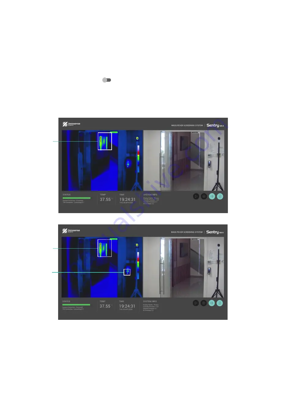
4.4.2  Mask 1 and 2

This function allows you to mask away a known hot area within the screening area to prevent the alarm from 
being activated. There are a total of 2 Masks available. If there are too many hot spots, you can use the Zone 
function instead to focus on the important area.

Setting the Mask

1.  Once you select the [Mask] 

 switch, the rest of the screen should be greyed out except the thermal 

image. 

2.  Set the Mask area by drawing the box on the screen to cover the hot spot.
3.  Repeat the same step for Mask 2 if a second mask is required.
4.  Select “Done” on top of the screen. From now on, do not move the camera or the TRS.

Mask 1

Mask 1

Mask 2

Summary of Contents for Sentry MK4

Page 1: ...User Guide Part No SM4 OMS 384 Ver 3 0 MASS FEVER SCREENING SYSTEM...

Page 2: ...System Overview 14 03 Getting Started 15 3 1 Powering up 15 3 2 User Interface 15 04 Configuring the System 16 4 1 Login Access Level 16 4 2 Operating Menu 16 4 3 TRS Thermal Reference Source 17 4 3...

Page 3: ...Screening Process 28 08 Advanced Functions 29 8 1 24HR Record 29 8 2 Rec on Detect 29 8 3 Storage Info 30 8 4 Export Video 31 8 5 IP Setting 32 8 6 Firmware Update 33 8 7 Ethernet Port 34 8 8 HTML Log...

Page 4: ...ables Do not cut or extend all supplied cables unless doing so is detailed in the installation guide Do not open or disassemble The unit is factory sealed to protect against atmospheric humidity suspe...

Page 5: ...on the product page at www omnisense systems com Product Disposal In accordance with European Union EU Waste Electrical and Electronic Equipment Directive 2002 96 EC WEEE all Electrical and Electroni...

Page 6: ...ent Omnisense Systems reserves the right to change the specifications of the hardware and software described in this guide at any time and without prior notice Omnisense Systems will not be held liabl...

Page 7: ...ximum protection Therefore it is recommended to read through the user guide before setting up the system This guide will provide you with the information you need to set up and operate the system 2 1...

Page 8: ...ered the mobile pedestal the following cables are pre installed in the mobile pedestal 1 Network Cable 2 USB Cable 3 Monitor Power Supply 4 Main Console Power Supply Mobile Pedestal optional TRS Tripo...

Page 9: ...guidelines may result in a false alarm trigger If there are small areas of hot objects that cannot be avoided use the onboard Mask function to exclude that area or Zone function to select a specific a...

Page 10: ...s how the Sentry MK4 components should be positioned in the screening area For mobile setup we recommend the system to be installed on our custom designed mobile pedestal This pedestal is designed wit...

Page 11: ...rce TRS communicates with the rest of the system via Bluetooth If a compatible touch monitor is not available a standard HDMI monitor and mouse can be used The camera unit is powered by PoE network po...

Page 12: ...connector of the mobile pedestal Slide in the quick release plate behind the Camera to the quick release adapter Remove the lens cap Mount the console on the mounting bracket on the pedestal Connect t...

Page 13: ...adphone 6 HDMI 7 USB 2 0 8 USB 3 0 9 Power 8 1 2 3 4 5 9 6 7 8 9 11 When powered on the Sentry MK4 MFSS graphical user interface GUI will appear on your monitor screen Connect the TRS unit to a power...

Page 14: ...14 2 8 System Overview...

Page 15: ...at its peak performance The system will be at its optimal performance when the status bar is constantly on green System Status Temperature Threshold Thermal Camera View Colour Camera View System Time...

Page 16: ...ted set of functions to perform screening operation effectively The permision to access the operating functions are granted by the Admin Please refer to Chapter 5 for more details To login select to a...

Page 17: ...TRS is within the white box If the TRS is not within sight adjust the position of the TRS or the camera unit 2 Once ready select the center of the TRS appear as a round spot Try to be as precise as yo...

Page 18: ...two options to choose from Celsius or Fahrenheit The Admin or User can select on either the Celsius or Fahrenheit buttons to toggle the temperature scale based on their preferences 4 3 4 TRS ID The T...

Page 19: ...hermal and day camera screens Switches to activate functions Display Palette 1 Privacy Levels 2 White Hot 3 Black Hot Choose the Privacy Level 1 mode for a more distinct view of the thermal image Sett...

Page 20: ...n use the Zone function instead to focus on the important area Setting the Mask 1 Once you select the Mask switch the rest of the screen should be greyed out except the thermal image 2 Set the Mask ar...

Page 21: ...ively from cold to hot In this mode a person below the trigger temperature will be in shades of White If the person is febrile the person will be in Red 3 Black Hot There are three colours White Red W...

Page 22: ...e Audio Alarm switch to right Select the Audio Alarm switch to the left to disable it There are 3 sound output buttons you can select on how you want the alarm to be emitted HDMI The alarm will be emi...

Page 23: ...ne Trigger Temp Mask 1 Mask 2 Audio Alarm and Playback To disable the User level from accessing any of the following functions select the Allow button of the function to the left Please logout after c...

Page 24: ...rights to access any of these functions These functions are sufficient for any user or frontline operator to perform the daily operation of the Sentry MK4 MFSS effectively 1 Set TRS see 4 3 1 2 Trigg...

Page 25: ...system only screen persons facing the camera we recommend outgoing traffic be channeled through other paths For the system to be at its optimal performance human traffic should be moving towards syste...

Page 26: ...26 Distance between Camera and TRS 10 16ft 3 5m not drawn to scale Figure 2 Camera TRS Hot background area e g entrance parking lots roads passing traffic or hot windows...

Page 27: ...27 Figure 3 Camera TRS Distance between Camera and TRS 10 16ft 3 5m not drawn to scale Hot background area e g entrance parking lots roads passing traffic or hot windows...

Page 28: ...creening Area via the stanchion or other barriers 2 Anyone who does not exhibit fever symptoms are able to safely pass through the Screening Area 3 A person with elevated body temperature will trigger...

Page 29: ...ction automatically record on screen video when a febrile person is detected by the system The system will record 15 seconds of video regardless if the febrile person is still detected within the zone...

Page 30: ...storage capacity 256GB and the amount of free storage of the storage device will then be shown after selecting the Storage Info button 2 If a video needs to be recorded select on Set Record Drive and...

Page 31: ...e video can be exported via another USB drive or a U3 micro SD card 2 Select the date of the recorded video followed by entering the start time and end time in hours and minutes 3 Select on the Export...

Page 32: ...to This field is also used to connect to the camera manually Changing the IP on this field does not change the IP address of the connected camera Once you changed the IP address select on the IP Save...

Page 33: ...systems com and save it in the drive 1 Insert the USB 3 0 drive into the USB 3 0 port of the console Select the Firmware Update button 2 Check to ensure that either the latest software of the camera...

Page 34: ...rt of your laptop 3 Insert the power cable HDMI and the USB cables into their respective ports of the console 4 Go to your web browser and enter the following link 172 16 9 200 8 8 HTML Login When you...

Page 35: ...ed earlier these functions will not be covered in this section 8 8 2 Security The Security function located at the Systems section of the Admin menu allows you to change the login settings of the Sent...

Page 36: ...684 2400x1800 Bitrate 2048 kbps 4096 kbps Information The tracking boxes are presently drawn and embedded on the existing video upon viewing by user There are no tracking boxes drawn on this video Def...

Page 37: ...e is still no power change the power adapter If step 2 fails proceed to step 3 Note The power adapter must be 12V 5W Console is faulty Step 3 Approach your dealer for assistance If you have no dealer...

Page 38: ...ble into the camera Wait for 30 seconds after rebooting IP address of the new camera IP and the current camera IP do not match Check the current and new camera IP addresses If one of it is different c...

Page 39: ...utomatic Pseudocolour specifically for fever screening User defined temperature trigger threshold Yes Synchronized dual sensor tracking Yes Yes Audio visual with intelligent febrile tracking U3 Micro...

Page 40: ...omnisense systems com...

Reviews: