[email protected] | Installation manual Omnicomm 2.0 terminals v2.2
7
.16 | 12
FIGURE 8
Connection utilising wireless readers from other manufacturers of CAN readers to the Omnicomm 2.0
Terminals is conducted in accordance with Figure 90.
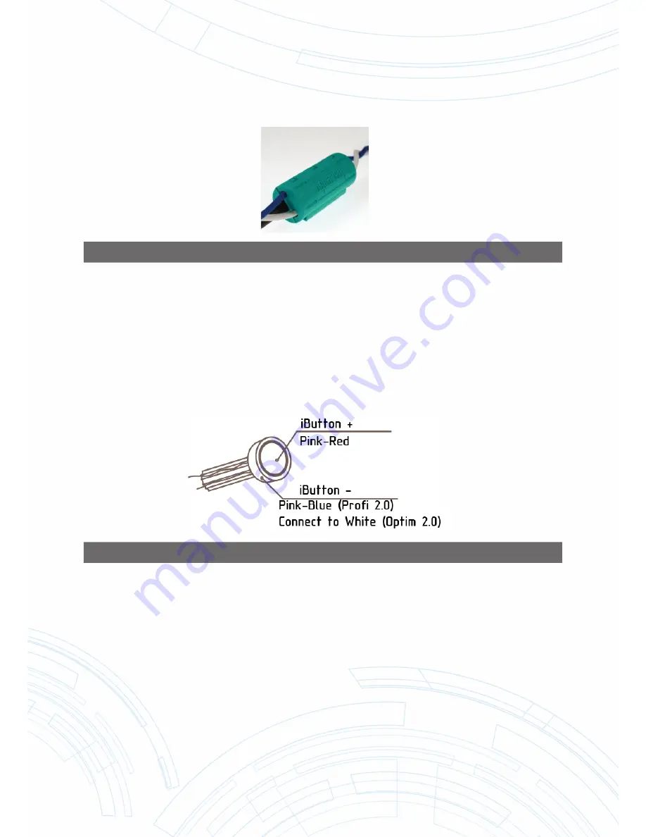
4.8 CONNECTION OF IBUTTON READER TO THE OMNICOMM PROFI2.0,
PROFI 2.0 WIFI AND OPTIM 2.0 TERMINALS
Make sure that the colours of the wires match the colours of the reader by testing the work of wire contacts
and reader housing.
Connect the iButton reader according to Figure 9.
FIGURE 9
It is possible to use EXSNET magnetic cards of X series with one wire and “em Marine” magnetic cards in
place of the iButton reader.
4.9 CONNECTION OF AN ACOUSTIC RADIATOR TO THE OMNICOMM
PROFI 2.0, PROFI 2.0 WIFI AND OPTIM 2.0 TERMINALS
Connect the yellow and red wire of acoustic radiator with controlled Terminal output, connect the brown
wire to the + 12 V/(+ 24V) on-board network or use the built-in power supply for the Omnicomm Pro
fi
2.0
Terminal, designed to power LLS fuel level sensors.
4.10 CONNECTION OF THE GSM ANSWER
-
CALL BUTTON TO OMNICOMM
PROFI 2.0, PROFI 2.0 WIFI AND OPTIM 2.0 TERMINALS
Connection of GSM answer-call button to Omnicomm Terminals is conducted in accordance with Figure 82.


