

4
M E C H A N I C A L I N S TA L L AT I O N
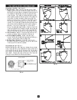
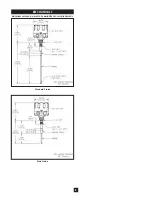
Standard, Food Grade and Stub Probe Mounting:
(See Figures 3 & 4)
1)
Select a mounting location in accordance with the Pre-
Installation Recommendations.
2)
If using a welded fitting, cut a hole into the side/top of the
vessel corresponding to the mounting connection (1-1/4”
NPT or 3/4” NPT). If using a mounting plate, cut a 2-1/2 inch
(64 mm) center hole and six 11/32 inch(9mm) mounting
holes (for 5/16” bolts) on a 7 inch (178 mm)bolt circle. Use
mounting plate as a template.
3)
Weld fitting or attach mounting plate to vessel wall.
4)
Insert probe through fitting. Do not use sealant tapes (e.g.
Teflon tape) or putties. When using the 1-1/4” NPT
connection, grease threads with anti-seize then thread unit
tightly into place by gripping and rotating housing. When
using the 3/4” NPT connection, thread unit tightly into place
by gripping and rotating 15/16 inch (24 mm) wrench flats
provided on fitting. Continuity between sensor mounting
point and vessel wall must be maintained to assure proper
probe operation.
Figure 4
Figure 3
DIMENSIONS ARE SHOWN IN INCHES WITH MILLIMETER EQUIVALENT IN BRACKETS
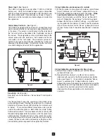
Factory Wiring:
The LV800 probe wires are connected to the backside of the
PCB. DO NOT alter this connection. Doing will likely cause
improper operation of the sensor.
Permanently Connected Equipment:
Disconnecting devices shall by included in the system installa-
tion. In installations were multiple circuits are used (i.e. inde-
pendent circuits for power input and output relay), individual
disconnects are required. The disconnects shall be within
close proximity of the equipment, accessible to operators, and
marked appropriately as the disconnect for the associated cir-
cuit. Assure the disconnect ratings are appropriately sized for
the circuit protected (See Specifications).
Circuit Separation:
Two cable entry locations are provided to aid in maintaining
separation of "hazardous live" (typically mains voltages such as
115VAC and 230VAC) and limited circuits (typically control
voltages less than 30Vrms or 42.4VDC). However, since the
LV800 single wiring compartment can not absolutely protect
against physical contact between multiple circuits, it is required
that all wiring used must have an insulation rating of 300V min-
imum, and a temperature rating of 80˚ C (176˚ F) minimum.
Protective Earthing:
Each LV800 is provided with a "protective conductor terminal"
which shall be terminated to the local earth ground potential to
eliminate shock hazard in the unlikely event of internal insula-
tion breakdown. Select wire size that can carry in excess of the
sum of all circuit's maximum amperage.
E L E C T R I C A L I N S TA L L AT I O N


