

5
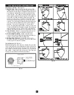
Figure 5
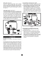
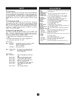
Power Input:
(See Figure5)
The LV800 is designed to accept either 115VAC or 230VAC
(factory set). Verify the intended voltage supply is compatible
with the voltage configuration indicated on the electronics and
the external nameplate. Connect power as shown in Figure 5.
Select wire size that can deliver suitable voltage and current for
the application.
Output Relay Contacts:
(See Figure 5)
The LV800 is equipped with one or two sets of isolated contacts
which indicates whether or not material is being detected with-
in the vessel. This output is also influenced by the selection of
the "fail-safe" switch as described in the "Calibration" section of
this manual. The designations on the circuit board relate to the
contact status when the material is "not" sensed and the fail-
safe switch is in the "low" mode. These contacts can be con-
nected to any type of control device, provided that ratings are
observed (See Specifications). Select wire size that can deliv-
er suitable voltage and current for the application.
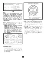
C A L I B R AT I O N
Sensitivity:
(See Figure 6)
Sensitivity is set in the field via a "Sense Adjust" 25-turn poten-
tiometer.
The “Sense Adjust” tunes the sensitivity of the LV800 to the
material being sensed. Rotating the adjustment in a clockwise
direction will increase the sensitivity making the material easier
to “detect”. There are two different procedures which can be
used in the calibration process. Both utilize the simple “2-Step
Calibration” procedure. One procedure sets the sensitivity with
the probe being exposed to the material, while the second pro-
cedure exposes the probe to free air only. Since the capaci-
tance being measured is directly related to the material being
sensed, the best results will be achieved by setting the calibra-
tion while the probe is exposed to the application material.
2-Step Calibration- probe exposed to free air only
1)
Rotate “Sense Adjust” clockwise just until the “Sense”
(yellow) LED turns on.
2)
Reposition “Sense Adjust” a number of turns counter-
clockwise with respect to the three described sensitivities
below (see Figure 7). It is desirable to reposition “Sense
Adjust” in accordance to “2-Step Calibration - probe
exposed to material” procedure once material can cover the
probe. Materials with high dielectric constants or conductiv-
ity, require the sensitivity adjustment further counter-
clockwise than those applications with low dielectric
constants.
2-Step Calibration- probe exposed to material
1)
While the probe is not covered with material, rotate “Sense
Adjust” clockwise just until “Sense” (yellow) LED turns on.
2)
Permit the application material to cover the probe.
While
counting the number of revolutions
, rotate “Sense
Adjust” counter-clockwise until the “Sense” (yellow) LED
turns off. Reposition “Sense Adjust” at the half way point
between the LED on and LED off settings. (e.g. After insert-
ing the probe into the material, if it takes 2 counter-clockwise
turns of “Sense Adjust” for the “Sense” (yellow) LED to turn
off, then “Sense Adjust” should be repositioned 1 clockwise
turn.)
Figure 6


