

6
Delay:
A potentiometer is provided for setting the time delay between
the time material is "sensed" (Yellow LED on) and the time the
relay contact output changes (Red LED on). Units have a 1-
turn potentiometer. A clockwise rotation will increase the delay
from .25 to 15 seconds. This adjustment minimizes false sig-
nals associated with temporary material shifts. The delay
between the time material is "not sensed" (Yellows LED off)
and the time the relay contact output changes (Red LED off) is
fixed at .25 seconds.
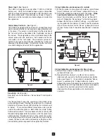
Fail-safe:
(see Figure 8)
The term fail-safe refers to the output signal condition which
occurs with a loss of power to the probe. A switch permits
selection of either low or high fail-safe.
High Fail-Safe:
The relay will de-energize when material
is sensed at high level or with power loss.
Low Fail-Safe:
The relay will de-energize when material
is below low level or with power loss. Note the designations
on the electronics label refer to the relay contact status
when no material is sensed and low fail-safe is selected
(Relay is de-energized). The designations are reversed
when no material is sensed and high fail-safe is selected
(Relay is energized).
Figure 7
LV800
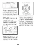
Indicators:
(See Figure 9)
1) Yellow LED
- Its status describes the "sensing" condition of
the LV800. Illumination indicated that the amount of capac-
itance established by the "Sense Adjust" has been detect-
ed. Its status is not affected by the time delay setting of the
fail-safe setting. This LED can only be seen when the cover
has been removed.
Figure 8
Figure 9
2) Red LED
- Its status describes the "operate/output" condi-
tion of the LV800. Illumination indicated the relay is in the
"operate/material sensed" condition. Its state is influenced
by the time delay setting but not by the fail-safe setting. This
LED is aimed at the lens in the cover so it can be seen with
the cover on or off.
3) Green LED
- Its status indicates “no material sensed” con-
dition of the LV800 in combination with the time delay set-
ting. If material has not been sensed for a long enough
time (as set by the time delay setting), this LED will be illu-
minated. The red and green LEDs should never be illumi-
nated at the same time. The green LED's state is not
affected by the fail-safe setting. This LED is also aimed at
the lens in the cover so that it can be seen with the cover
on or off.


