background image

HHTQ35 Digital Torque Gauges 


User’s Guide 


14


Selection Description 

N Units 

Output format includes the value and unit of measure. Clockwise values have 
positive polarity, counter-clockwise values have negative polarity. 

Numeric Only 

Output format includes the value only. Polarity same as above. 

Invert Polarity 

Clockwise values have negative polarity, counter-clockwise values have positive 
polarity. May be selected in addition to the N Units / Numeric Only 
selection. 

Omit Polarity 

Both directions are formatted with positive polarity. May be selected in addition to 
the N Units / Numeric Only selection. 


Individual data points may be transmitted by pressing 

DATA

.  


10   CALIBRATION  


10.1 Initial Physical Setup 

 
The sensor should be mounted vertically to a test stand or fixture rugged enough to withstand a load 
equal to the full capacity of the instrument. Vertical orientation is preferable to avoid side loading, which 
can affect the readings. Suitable certified calibration equipment is required, and caution should be taken 
while handling such equipment.  

 
10.2 Calibration Procedure 
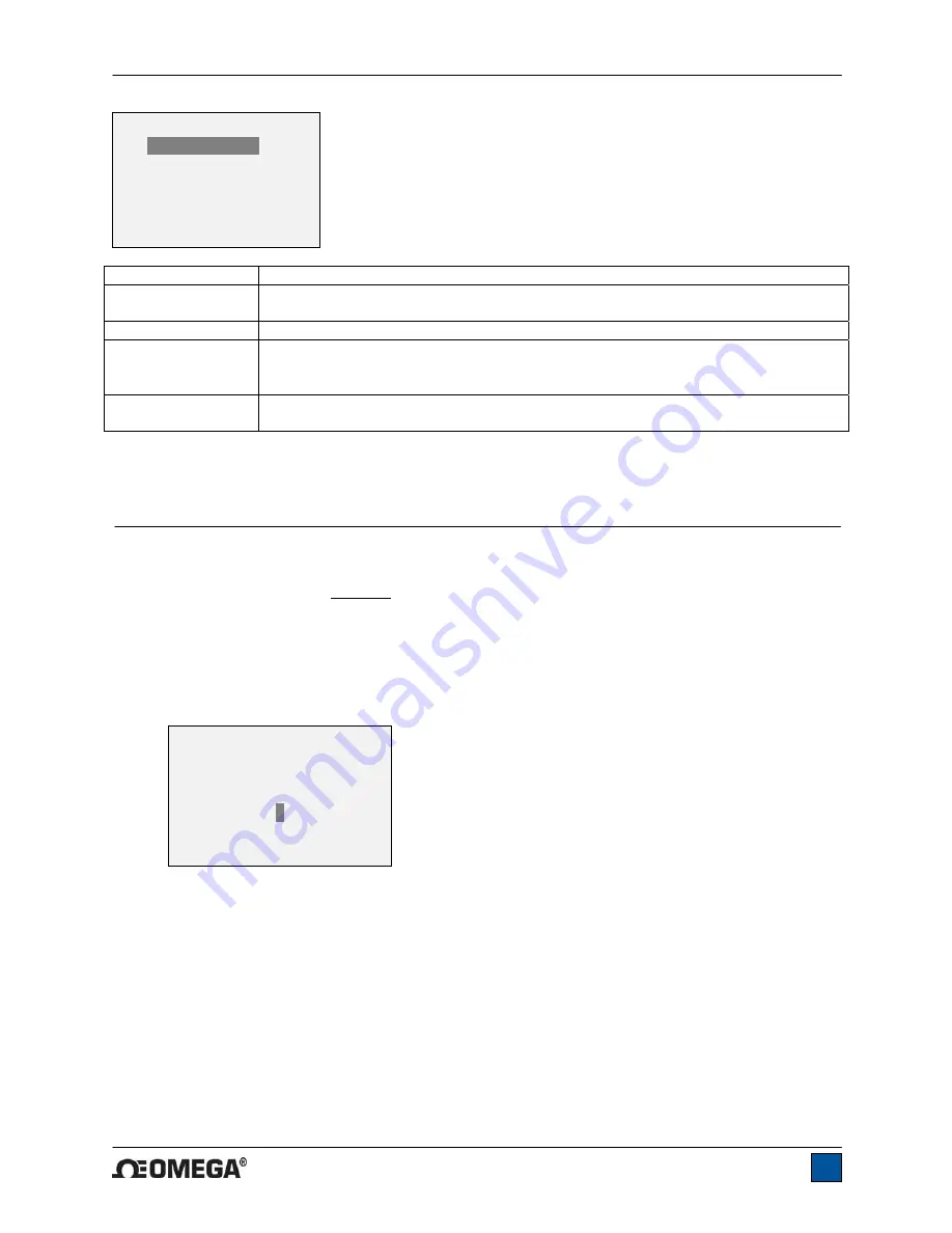
 

1. Select 

Calibration

 from the menu. The display will appear as follows:  


The sensor can be calibrated at up to 10 points in each direction. Enter the number of calibration 
points for each direction. At least one point must be selected for each direction. 


Note:

 To achieve the accuracy specification of ±0.5% of full scale, it is recommended to calibrate 

the sensor at 5 or more even increments in both the clockwise and counter-clockwise directions. 
For example, a sensor with capacity of 50 lbFin should be calibrated at 10, 20, 30, 40, and 50 
lbFin loads in each direction. 


2.  To escape the 

Calibration

 menu at any time, press 

ESCAPE

. The display will appear as follows: 

DATA FORMAT 

*    

N Units 

     Numeric Only 
     Invert Polarity 
     Omit Polarity 
  

CALIBRATION 

ENTER # CAL POINTS 

(1 TO 10) 

CLOCKWISE: 

COUNTER-CLOCKWISE: 

Summary of Contents for HHTQ35

Page 1: ...HHTQ35 Digital Torque Gauges...

Page 2: ...HHTQ35 Digital Torque Gauges User s Guide 1...

Page 3: ...operation instructions Dimensions and specifications are also provided For additional information or answers to your questions please do not hesitate to contact us Our technical support and engineeri...

Page 4: ...ng operation 1 Never operate the gauge if there is any visible damage to the AC adapter or the gauge itself 2 Ensure that the gauge is kept away from water or any other electrically conductive liquids...

Page 5: ...s 1 When battery life is greater than 75 the following indicator is present 2 When battery life is between 50 and 75 the following indicator is present 3 When battery life is between 25 and 50 the fol...

Page 6: ...nt Side loading or off center loading can damage the instrument whether power is turned on or off 3 2 Mounting to a plate The indicator portion of the gauge can be mounted to a plate with four thumb s...

Page 7: ...left indicates counter clockwise load If set points are enabled triangular markers are displayed for visual convenience This indicator reflects the actual load which may not correspond to the primary...

Page 8: ...el Secondary Function Powers the gauge on and off Press briefly to power on press and hold to power off Active only when the home screen is displayed ENTER Various uses as described in the following s...

Page 9: ...ert back to the sub menu item or press ESCAPE to revert back to the sub menu item without saving Press ESCAPE to revert one step back in the menu hierarchy until back into normal operating mode Refer...

Page 10: ...e average of a single value is the value itself To access digital filter settings select Filters from the menu The display will appear as follows Two filters are available Current Reading Applies to t...

Page 11: ...the current live load 9 COMMUNICATIONS Communication with the HHTQ35 is achieved through the micro USB port located along the left side of the housing as shown in the illustration in the Power sectio...

Page 12: ...e connecting an Omega USB device 5 After Windows as restarted plug in the device The following will occur Windows 7 Operating Systems When the Omega USB device has been plugged into a USB port the dri...

Page 13: ...Torque Gauges User s Guide 12 Select No not this time then click Next 6 The next screen appears as follows Select Install the software automatically Recommended then click Next 7 The next screen appe...

Page 14: ...d 9 2 Communication Settings To set up communication settings select USB Settings from the menu The screen appears as follows Communication settings are permanently set to the following Data Bits 8 St...

Page 15: ...ity of the instrument Vertical orientation is preferable to avoid side loading which can affect the readings Suitable certified calibration equipment is required and caution should be taken while hand...

Page 16: ...ar as follows If failed 5 The following screen appears after the offsets have been calculated Keep the sensor in a vertical position as explained in Section 10 1 Attach weight fixtures brackets hooks...

Page 17: ...he UP and DOWN keys to adjust the torque value as required The torque values default to even increments as indicated by the previously entered number of data points described in Step 1 Then press ENTE...

Page 18: ...isplayed at the start of calibration if a disallowed unit is selected Ensure that the load is not swinging oscillating or vibrating in any manner Then try again The calibration load does not match the...

Page 19: ...e will ignore the Automatic Shutoff setting and remain powered on until the POWER key is pressed 11 2 Backlight Several initial settings are available upon powering on the gauge To access these settin...

Page 20: ...The Set Point alert can be configured to be either a momentary tone or a continuous tone until the load is restored to a value between the set points To configure the functions for which audible tone...

Page 21: ...alarms calibration Safe overload 150 of full scale display shows OVER at 110 and above Weight 1 8 lb 0 8 kg Included accessories Carrying case AC adapter battery USB cable resource CD USB driver user...

Page 22: ...x 0 01 14 x 0 01 HHTQ35 50Z 50 x 0 05 36 x 0 05 36 x 0 05 HHTQ35 12 192 x 0 2 12 x 0 01 135 x 0 1 HHTQ35 50 800 x 1 50 x 0 05 570 x 0 5 HHTQ35 100 1600 x 2 100 x 0 1 1150 x 1 12 4 Dimensions IN MM 3 9...

Page 23: ...HHTQ35 Digital Torque Gauges User s Guide 22...

Page 24: ...HHTQ35 Digital Torque Gauges User s Guide 23 M 5086 0712...

Reviews: