HHTQ35 Digital Torque Gauges
User’s Guide
10
Either one, two, or none of the set points may be enabled. To toggle between the clockwise and counter-
clockwise directions, press the
DIRECTION
key.
If two set points have been enabled, they are displayed in the upper left corner of the display. If only one
set point has been enabled, the word “OFF” will appear in place of the value. If no set points have been
enabled, the upper left corner of the display will be blank.
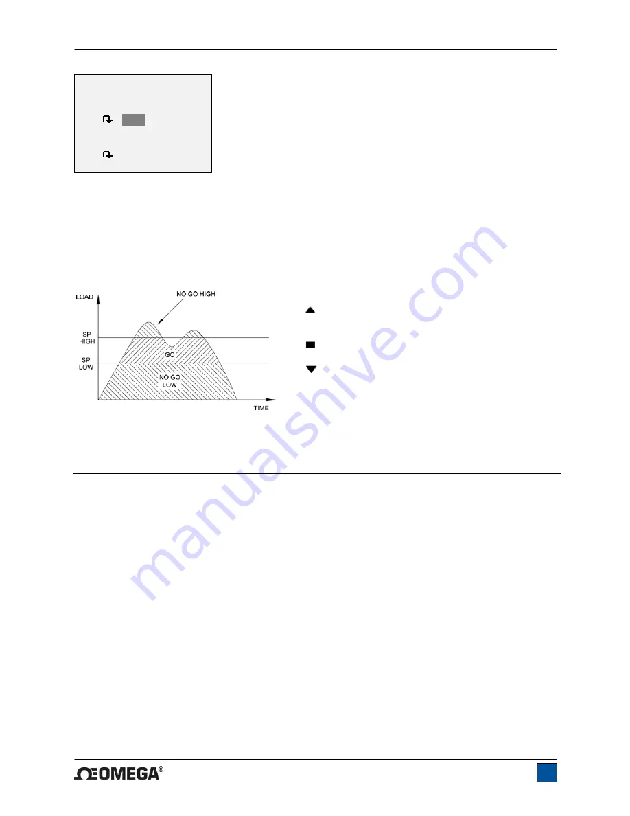
When set points are enabled, the following indicators are shown to the left of the primary reading:
– the displayed value is greater than the upper
load limit (NO GO HIGH)
– the displayed value is between the limits (GO)
– the displayed value is less than the lower load
limit (NO GO LOW)
Note:
Set point indicators reference the displayed reading, not necessarily the current live load.
9 COMMUNICATIONS
Communication with the HHTQ35 is achieved through the micro USB port located along the left side of
the housing, as shown in the illustration in the
Power
section. Communication is possible only when the
gauge is in the main operating screen (i.e. not in a menu or configuration area). The current reading is
transmitted from the gauge when the
DATA
key is pressed.
9.1 Installing the USB driver
Caution!
It is recommended that the USB driver be installed before physically connecting the tester to the
PC with a USB cable.
1. Insert the Resource CD supplied with the gauge into the CD/DVD drive in the computer. Then,
navigate in
Windows Explorer
or
My Computer
to the following folder on the CD:
“Windows_XP_S2K3_Vista_7”.
2. Run the installer application “OmegaUSBInstaller.exe” by double-clicking it. When the program
launches, one of the following windows will appear, depending on the operating system:
SET POINTS
Upper Disabled
* Upper Enabled
5.00
Lower Disabled
* Lower Enabled
3.50


