


Model DFG-RS5 Digital Force / Torque Indicator
User’s Guide
16
Press
ENTER
to delete the value. To exit
Delete
mode, press
DELETE
again. Any number of readings
may be individually deleted, however, all readings may also be cleared simultaneously. Refer to the
Clear
All Data
section for details.
8.2 Statistics
Statistical calculations are performed for the saved values. Calculations include number of readings,
minimum, maximum, mean, and standard deviation.
8.3 Output Data
Press
ENTER
to output data to an external device. The display will show, “SENDING DATA…”, then
“DATA SENT”. If there was a problem with communication, the display will show, “DATA NOT SENT”.
Saved data can be downloaded by some Omega data collection programs. Refer to their respective
user’s guides for details.
8.4 Output Statistics
Press
ENTER
to output statistics to an external device. The display will show, “SENDING STATS…”, then
“STATS SENT”. If there was a problem with communication, the display will show, “STATS NOT SENT”.
8.5 Output Data & Stats
Press
ENTER
to output data and statistics to an external device. The display will show, “SENDING
DATA”, then “SENDING STATS…”, then “DATA SENT”, then “STATS SENT”. If there was a problem with
communication, the display will show, “DATA NOT SENT” and/or “STATS NOT SENT”.
8.6 Clear All Data
Press
ENTER
to clear all data from the memory. A prompt will be shown, “CLEAR ALL DATA?”. Select
Yes
to clear all the data, or
No
to return to the sub-menu.
Shortcut for clearing all data:
In the main menu, highlight
Memory
and press
DELETE
. The same
prompt will be shown as above.
For output of data and/or statistics, RS-232 or USB output must be enabled. Data formatting is
<CR><LF> following each value. Units can be either included or excluded. Output of data via the Mitutoyo
output is possible, however, output of statistics is not. Refer to the
Communications
section for details.
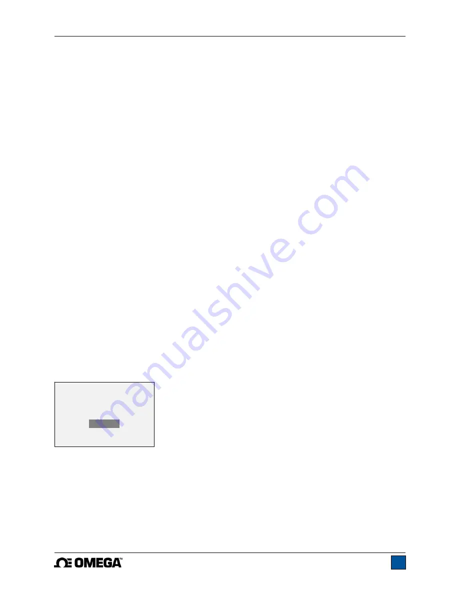
Note:
Data is not retained while the gauge is powered off. However, the gauge protects against
accidental or automatic power-off. If manually powering the instrument off, or if the inactivity time limit for
the
Automatic Shutoff
function has been reached, the following warning message appears:
If no option is selected, this screen will be displayed indefinitely, or until battery power has been depleted.
*** WARNING ***
DATA IN MEMORY
WILL BE LOST
CANCEL
POWER OFF


