background image

Model DFG-RS5 Digital Force / Torque Indicator    

User’s Guide 


14


After the parameters have been configured and the menu has been exited, press 

MODE

 until 

AVG

 is 

displayed. Then press 

ZERO

. Average mode is now armed, and the averaging sequence will commence 

when the trigger load has occurred. The current status of the average sequence is displayed below the 
primary reading, as follows: 
 

Step Status 

Abbreviation 

Description 

TRIG WAIT 

The trigger load has not yet occurred. 

INIT DLY 

The initial delay is currently taking place. 

AVERAGING 

The indicator is collecting readings. The status will be flashing until 
averaging has been completed. 

AVRG DONE 

Averaging has been completed. The average load is displayed in the 
primary reading. 

 
At the completion of the averaging sequence, the peak values are retained until 

ZERO

 is pressed. 

Another averaging sequence may be started after 

ZERO

 has been pressed. To exit Average mode, press 

MODE

 and select the desired measuring mode. 


7.5 External Trigger (ET) 

This mode of operation is useful for measuring electrical contact activation load as well as 
synchronization of multiple instruments for a “snapshot” view of applied loads. It is possible to capture the 
reading with a normally open contact (high to low transition of the trigger signal) or a normally closed 
contact (low to high transition).  
 
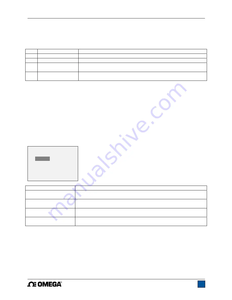
Before the parameters of External Trigger Mode can be configured, it must be enabled. To do so, enter 
the main menu, select 

External Trigger

, scroll to one of the four available options and press 

ENTER

The options are as follows: 


Option Description 

Momentary High 

 Low 

The display will freeze the captured reading until 

ZERO

 is pressed. Applies 

to a high to low transition of the trigger signal.  

Momentary Low 

 High 

The display will freeze the captured reading until 

ZERO

 is pressed. Applies 

to a low to high transition of the trigger signal. 

Maintained High 

The display will show the captured reading only for as long as a high signal 
is maintained.  

Maintained Low 

The display will show the captured reading only for as long as a low signal 
is maintained.  

 
After the selection has been made and the menu has been exited, press 

MODE

 until 

ET

 is displayed. 

External Trigger mode is now armed. Refer to the pin diagram in the 

Communications

 section for 

connection information. To exit External Trigger mode, press 

MODE

 and select the desired measuring 

mode. 
 

Note: 

As long as external trigger has been enabled, it is still active even if the indicator is in 

Real Time


mode. After the display freezes, any programmed set points will be active. However, if the indicator is in 

External Trigger

 mode, any programmed set points will be inactive.  


EXTERNAL TRIGGER 


  * 

Disabled 

    Momentary Hi->Lo 
    Momentary Lo->Hi 
    Maintained High 
    Maintained Low 

Summary of Contents for DFG-RS5

Page 1: ...Model DFG RS5 Digital Force Torque Indicator...

Page 2: ...Model DFG RS5 Digital Force Torque Indicator User s Guide 1...

Page 3: ...Guide provides setup safety and operation instructions Dimensions and specifications are also provided For additional information or answers to your questions please do not hesitate to contact us Our...

Page 4: ...icator and connected to another without the need for re calibration or re configuration All such data is saved within a PCB located inside the smart connector The model number serial number and capaci...

Page 5: ...oper Usage Read through the following safety instructions thoroughly before using the DFG RS5 with a sensor 1 Note the sensor s capacity before use and ensure that the capacity is not exceeded Produci...

Page 6: ...or to a test stand work bench or other piece of equipment 2 POWER The DFG RS5 is powered either by an 8 4V NiMH rechargeable battery or by an AC adapter Since these batteries are subject to self disch...

Page 7: ...lace with a click Fig 3 1 Appropriate orientation of the connector To release the connector press both buttons on either side of the indicator housing to release the sensor as shown in Fig 3 2 below P...

Page 8: ...ion for detailed hole information and locations 3 4 Installing the USB driver If communicating via USB install the USB driver provided on the Resource CD Caution Install the USB driver before physical...

Page 9: ...f a sensor is not plugged in this value will be replaced by a message as follows SENSOR NOT CONNECTED 4 Load bar Analog indicator to help identify when an overload condition is imminent The bar increa...

Page 10: ...The number of stored data points in memory up to 1 000 Displayed only if Memory Storage is enabled for the DATA key 8 Battery AC adapter indicator Either the AC adapter icon or battery power icon will...

Page 11: ...and DOWN keys to scroll through the items The current selection is denoted with clear text over a dark background Press ENTER to select a menu item then use UP and DOWN again to scroll through the su...

Page 12: ...at its lowest value for best performance and the displayed reading filter at its highest value for best stability 6 SET POINTS 6 1 General Information Set points are useful for tolerance checking pass...

Page 13: ...HIGH the displayed value is between the limits GO the displayed value is less than the lower load limit NO GO LOW Note Set point indicators and outputs reference the displayed reading not necessarily...

Page 14: ...rce torque sensors respectively Same as above but for tension counter clockwise readings 7 4 Average Mode AVG Average mode is used to obtain an average load reading over a specified period of time App...

Page 15: ...signal or a normally closed contact low to high transition Before the parameters of External Trigger Mode can be configured it must be enabled To do so enter the main menu select External Trigger scr...

Page 16: ...played reading The record number will increment each time DATA is pressed If DATA is pressed when memory is full the message MEMORY FULL will be flashed at the bottom of the display and a double audio...

Page 17: ...external device The display will show SENDING DATA then SENDING STATS then DATA SENT then STATS SENT If there was a problem with communication the display will show DATA NOT SENT and or STATS NOT SEN...

Page 18: ...to transmit individual data points or to commence an automatic output sequence see Automatic Output sub section for details Single point or continuous data may also be requested via ASCII commands fr...

Page 19: ...c output of data may be initiated by pressing DATA or by sending the appropriate ASCII command from an external device see Command Set sub section for details The icon will become animated signaling t...

Page 20: ...pend on several factors described in the table below Output functions always reference the primary reading on the display regardless of the current mode Pin No Description Input Output 1 Signal Ground...

Page 21: ...al device through the RS 232 or USB channel The following is a list of supported commands and their explanations All commands must be terminated with a Carriage Return character or with a Carriage Ret...

Page 22: ...set point value if both values are set to the same polarity USB RS 232 Communication FULL USB RS 232 transmission with units NUM USB RS 232 transmission without units only numeric values AOUTn Auto t...

Page 23: ...re version the last field shows the remaining battery power B0 full charge B3 minimum power All other fields show the status of settings and features using the same abbreviations as the commands to se...

Page 24: ...th capacity of 10 lbF should be calibrated at 2 4 6 8 and 10 lbF loads in each direction 2 To escape the Calibration menu at any time press ESCAPE The display appears as follows Selecting Cancel will...

Page 25: ...rs as follows Apply a weight equal to the full scale of the instrument then press ENTER 8 After displaying Please wait the display appears as follows Remove the load applied in Step 8 leave the fixtur...

Page 26: ...a points selected 10 After all the compression calibration points have been completed the display appears as follows Press ENTER 11 At the completion of the tension calibration the display appears as...

Page 27: ...ension signal calibration cannot continue Verify that the tension compression indicator on the home screen properly corresponds to the load direction and switch the signal leads if required The entere...

Page 28: ...onnected Then highlight Sensor Lock in the sub menu and press ENTER After configuration if a different sensor is connected the display appears as follows Connect the correct sensor then press ENTER to...

Page 29: ...12 1 Automatic Shutoff The indicator may be configured to automatically power off following a period of inactivity while on battery power Inactivity is defined as the absence of any key presses or loa...

Page 30: ...d in minutes via the Set Minutes parameter Available settings 1 10 in 1 minute increments Note If the AC adapter is plugged in the indicator will ignore these settings and keep the backlight on 12 3 L...

Page 31: ...on the sensor series The default mode is Real Time regardless of sensor 12 6 Restore Default Settings Default factory settings can be restored by selecting Restore Defaults from the menu The settings...

Page 32: ...zFin kgFm kgFmm gFcm Nm Ncm Nmm depending on sensor Outputs USB RS 232 Fully configurable up to 115 200 baud Includes Gauge Control Language 2 for full computer control Mitutoyo Digimatic Serial BCD s...

Page 33: ...ging Time sec 5 0 External Trigger Disabled DATA Key Functions RS 232 USB Output Enabled Mitutoyo Output Disabled Memory Storage Enabled Backlight Auto Minutes 1 Serial USB RS 232 Output Selected Enab...

Page 34: ...Model DFG RS5 Digital Force Torque Indicator User s Guide 33...

Page 35: ...Model DFG RS5 Digital Force Torque Indicator User s Guide 34 M 5251 1017...

Reviews: