86
EPOCH 4PLUS
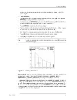
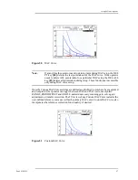
Once the curve is complete, the Reference Gain function can be activated by pressing
[2
nd
F], [GAIN] (REF DB). This key sequence locks in a reference gain level and allows
scanning gain to be added or subtracted to accommodate specific applications. For
example, if it is required to evaluate any reflector that exceeds 50% of the DAC level, 6 dB
of scanning gain can be added. In this manner, the DAC curve when used in conjunction
with the Amplitude DAC display and DAC alarm becomes an easy reference to determine
if an indication exceeds the evaluation level. Note that the additional scanning gain cannot
be added to the original reference gain level as this would change the calibration and
invalidate the DAC curve.
9.2.2
Special Considerations for JIS Z3060 DAC Curves
In general, the instructions in Section 9.2.1 apply to the construction of all DAC curves.
However, there are some special provisions that address the requirements of JIS Z3060.
These considerations are listed below.
•
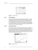
Because of the large number of curves drawn for the JIS DAC mode, it is possible to
temporarily add in 6, 12, 18, or 24 dB of additional gain while constructing the DAC
curve set. The purpose of this feature is to facilitate construction of additional curves
when testing at longer ranges. Once construction of the curve set has begun, add up to
24 dB of additional gain through repeated presses of the [GAIN] key. In order to make
clear that gain has been added while constructing the curve, the gain appears as
follows: “GAIN 46.2 dB + 6,” “GAIN 46.2 dB + 12,” and so on. Once the curve set is
completed, the gain is reset to its original level (46.2 dB in this example).
•
It is also possible to change Angle, Material Thickness, Zero Offset, and Gain in the
normal manner when in the JIS DAC mode. Be careful when adjusting these
parameters to ensure that the relationship of DAC curves to material thickness or
distance is not unintentionally altered.
•
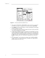
Any of the six curves can be used to trip the alarm when in the JIS DAC mode.
Additionally, you can set the alarm to positive or negative. To select which curve will
be used as the alarm reference level, first activate JIS DAC and then use the [F4] and
[F5] function keys to select which curve to use for the alarm threshold. The selected
curve appears as a double thickness line. Once a curve has been selected, an alarm can
be activated and set to be either positive or negative threshold detection by pressing
[2
nd
F], [GATE 1] (ALARM 1) and following the prompts.
•
When the JIS DAC mode is active, the amplitude (level) of a gated signal is always
displayed as a percentage (% DAC or dB DAC) with respect to the selected curve. If
a different curve is selected, the displayed amplitude changes accordingly.
9.2.3
Saving and Recalling DAC Curves
DAC curves are saved and recalled in the same manner as any general waveform/
calibration. With DAC mode active, use the [SAVE WAVE] key to save the entire setup
in the datalogger. When a setup that was stored with a DAC curve is recalled, the
instrument automatically comes up in the DAC mode.
Summary of Contents for Panametrics Epoch 4 Plus
Page 4: ...EPOCH 4PLUS...
Page 10: ...EPOCH 4Plus...
Page 18: ...8 EPOCH 4PLUS...
Page 40: ...30 EPOCH 4PLUS...
Page 50: ...40 EPOCH 4PLUS...
Page 54: ...44 EPOCH 4PLUS...
Page 92: ...82 EPOCH 4PLUS...
Page 172: ...162 EPOCH 4PLUS...

