56
EPOCH 4PLUS
4. Press [VEL] to enter an approximate velocity for the test material and adjust the value
with the function keys or the [ ] and [ ] keys. If the velocity value is unknown, find
a value for the material being tested in Appendix B - Sound Velocities of this manual.
5. Press [RANGE] to set the range and then adjust the value using the function keys or
the [ ], [ ], [
], or [
] keys.
6. Press [2nd F], [ANGLE] (THICKNESS) to set the material thickness to 0.00" or
0.00 mm. Press [F1] or use the [ ] key to adjust the value to zero.
7. Press [ZERO OFFSET] to set the zero offset value to 0.00
µ
sec. Press [F1] or use the
[ ] or [
] keys to bring the initial pulse to the left side of the instrument screen.
8. Press [ANGLE] to enter the correct refracted angle for the probe (0 for a straight beam
or 90
o
probe, 45 for a 45
o
, etc.) Use the function keys to access preset values or adjust
in 0.1
o
adjustments using the [ ] and [ ] keys.
9. Once the transducer is coupled to the block, adjust the pulser and filter settings to
create a clean A-Scan. Press [PULSER] multiple times to allow access to the various
pulser and filter functions. Alternately, press [2nd], [PULSER] (FILTER) to go
directly to the filter settings. Adjust each function with the function keys or the [ ],
[ ], [
], and [
] keys.
Note:
Refer to Chapter 4, Adjusting the Pulser Receiver, for information on how to
set the pulser and filter parameters.
7.2
Calibrating with a Straight Beam Transducer
Use Olympus NDT
TM
transducer part number A109S-RM, with a frequency of 5.0 MHz
and an element diameter of 0.50" (13 mm) to perform the sample Straight Beam
calibration. The calibration requires a test block with two known thicknesses, made from
the material to be measured. Ideally the two thicknesses should represent thicknesses that
are both below and above the expected thickness of the material being inspected.
For this example, we are using Olympus NDT standard 5-step steel test block part number
2214E. The steps measure 0.100", 0.200", 0.300", 0.400", and 0.500".
Note:
If the EPOCH 4PLUS is set to metric units, the calibration process is exactly
the same, except that the entries below will be in millimeters rather than
inches.
To calibrate using a Straight Beam transducer, follow these steps:
1. Follow the initial set-up procedure outlined above. Connect the transducer to an
appropriate cable and then connect the cable to either of the transducer posts on the
EPOCH 4PLUS.
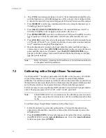
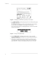
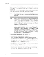
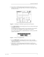
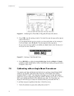
2. Press [CALIBRATION]. A Cal symbol appears to the right of the A-Scan, signifying
the EPOCH 4PLUS is in the Auto-Calibration mode. To exit the Auto-Calibration
mode at any point, press [ENTER].
Summary of Contents for Panametrics Epoch 4 Plus
Page 4: ...EPOCH 4PLUS...
Page 10: ...EPOCH 4Plus...
Page 18: ...8 EPOCH 4PLUS...
Page 40: ...30 EPOCH 4PLUS...
Page 50: ...40 EPOCH 4PLUS...
Page 54: ...44 EPOCH 4PLUS...
Page 92: ...82 EPOCH 4PLUS...
Page 172: ...162 EPOCH 4PLUS...


