background image

TIP

You can use only alphanumeric characters and symbols for folder and file names. The

Japanese characters cannot be used. And some symbols cannot be used for the folder
and file names.

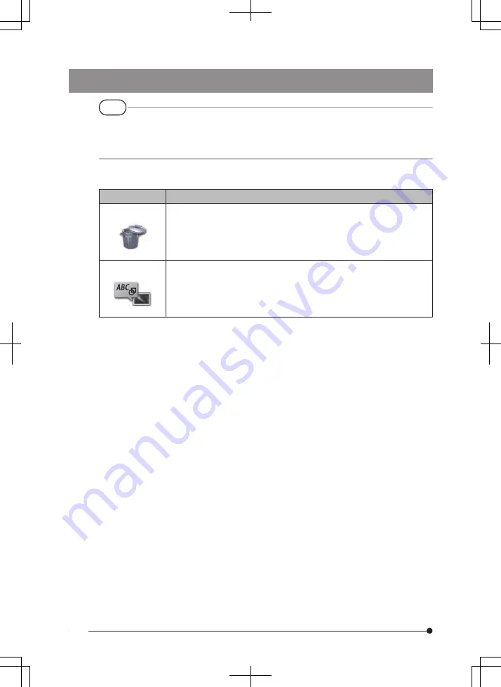
The following settings can be applied from the view screen menu.

Menu

Available settings

DELETE

Deletes the recorded image.

CANCEL

: Do not delete image.

EXECUTE : Delete image.

Deletes the image displayed on the view screen.

NOTE

Inputs the note information (TEXT/MARK/FREE DRAWING) to the
desired position on the screen (view screen for still image only).

You can input note information (TEXT/MARK/FREE DRAWING) on the
still image that is being played back.

64

Summary of Contents for IPLEX G Lite

Page 1: ... INSTRUCTIONS IPLEX G Lite INDUSTRIAL ENDOSCOPE IV9420GL IV9435GL IV9620GL IV9635GL IV96100GL Industrial Endoscope B5A 2438 20 MM3014 02 ...

Page 2: ... Distributed by Manufactured by Shinjuku Monolith 2 3 1 Nishi Shinjuku Shinjuku ku Tokyo 163 0914 Japan www olympus global com ...

Page 3: ......

Page 4: ...lature 13 2 1 Nomenclature 13 2 2 Distal end optical adapter nomenclature 14 2 3 LCD monitor nomenclature 15 3 Pre operation preparation and inspection 22 3 1 Preparing the power supply 22 1 Using the battery 22 2 Using the AC adapter 23 3 Charging the battery 23 3 2 Attaching and removing the optical adapter 24 3 3 Inserting removing the SDHC or micro SDHC card 26 3 4 Attaching removing the hand ...

Page 5: ... level 33 4 3 Turning ON the light 34 1 Checking the lighting of the illumination at the distal end of the insertion tube 34 4 4 Operating the instrument 34 4 5 Observing the inspection object 37 4 6 Adjusting the image display 38 1 Still image Freeze 38 2 Enlarging the image Zoom 38 3 Adjusting the brightness 39 4 7 Switching the folder on the live screen 40 4 8 Recording images 41 1 Image record...

Page 6: ...2 4 11 Displaying live images on the external monitor 52 4 12 Displaying live images on the mobile terminal 52 1 Connecting the USB wireless LAN adapter 53 2 Enabling the USB wireless LAN adapter from the menu 53 4 13 Using recorded images on a PC 53 5 Menu operations and functions 54 5 1 Menu operations 54 5 2 Using the live screen freeze screen 55 1 Initial setting menu 55 2 Inputting a title 59...

Page 7: ...ereo optical adapter 71 4 Selecting a registered stereo optical adapter 76 5 Checking measurement values 76 6 Observing the measurement area on the live screen 79 7 Measuring the distance to the measurement area by spot ranging 80 8 Measurement 82 9 Measurement screen 83 10 Measurement method types 85 11 Specification of measurement points 87 7 Observation of special light 88 7 1 Replacing the LED...

Page 8: ... 4 Cleaning the LCD monitor 97 5 Cleaning of other units 97 9 4 Storage precautions 97 10 Specifications 98 10 1 Operating environment 98 10 2 Other specifications 99 1 Other specifications 99 2 External application standard 102 3 Software license information 103 4 Using open source software 103 5 AVC Patent Portfolio License 103 10 3 Optical adapter specifications 104 1 For 4 mm type insertion tu...

Page 9: ...If you have any questions about any information in this instruction manual please contact Olympus Product configuration For the configuration of devices required by this instrument and devices that can be used in combination with it see System chart page 106 in Appendix Note that use of this instrument in combination with options or separately available items other than System chart does not only ...

Page 10: ...andling this instrument The information is supplemented by dangers warnings and cautions given in each chapter The safety cannot be ensured when the instrument is used in ways that are not specifically described DANGER Never use the instrument for observing inside of the human or animal cavity Otherwise death or the serious injury of the person or animal may result Never use the instrument in the ...

Page 11: ...he distal end and the insertion tube right after using this instrument in high temperature environments as the temperature does not cool down immediately Otherwise you may get burned Do not grip the control for a prolonged period of time when using the unit under a high temperature Otherwise it may cause low temperature burns Take precautionary measures such as wearing protective gloves to prevent...

Page 12: ...g the distal end Otherwise the angulation section may be damaged Always attach the optical adapter before using this instrument If you use the instrument without attaching the optical adapter to the insertion tube parts screws etc are easily deformed due to contact with hard objects etc If the insertion tube parts are deformed the optical adapter cannot be attached or may fall off Never use the op...

Page 13: ... the doors of the battery compartment and other interfaces are tightly closed Do not use or store the instrument in an environment where it is submerged in water Do not subject the LCD monitor to strong impact strong pressure or to scratching by a hard or pointed object Otherwise the LCD monitor may be cracked or scratched or the damaged monitor may cause personal injury Use SDHC card and microSDH...

Page 14: ...g a UV LED unit or IR LED unit check that the LED icon lights up on the live screen or other screens Use the equipment in accordance with the regulations for Workers Health and Safety if any Information of IEC62471 RISK GROUP2 CAUTION Possibly hazardous optical radiation emitted from this product Do not stare at operating lamp May be harmful to the eyes NOTICE UV emitted from this Product Minimize...

Page 15: ... damage the instrument Do not allow any liquids other than water saltwater machine oil or diesel oil to be attached to the insertion tube Otherwise the insertion tube may be damaged Note the following precautions when handling the battery compartment door and interface doors Do not open or close the doors when there is water on the surrounding surfaces Do not open or close covers with your wet han...

Page 16: ...er immediately and stop using it Contact Olympus If the battery charger does not complete recharging the battery in the specified recharging time stop attempting to recharge the battery Do not allow the battery compartment to become deformed and never put any foreign object into it Do not allow metal or water or any other fluid to get into the battery compartment or onto the battery terminals If a...

Page 17: ...not use charge or store the battery in areas exposed to direct sunlight in a closed automobile in the sun or near a heater etc Do not use a battery if it shows any irregularity such as fluid leak discoloration deformation abnormal odor or other abnormality Do not immerse the battery in fresh water or sea water or allow the battery to get wet When disposing of a battery be sure to do so in accordan...

Page 18: ...of the safety symbols and always use the product in the safest possible manner If labels are missing or if their contents are illegible contact Olympus Rating model serial number precautions Possibly hazardous optical radiation emitted from this product See page 6 Conformity label CAUTION Rating plate caution plate 10 ...

Page 19: ...Instruction manual 1 Carrying case 1 1 For procedures to store the instrument in the carrying case refer to the label which describes the storing procedures attached to the inner surface of the top lid of the carrying case 1 Storing the optical adapter case The optical adapter case can be used to store the following items Optical adapter SDHC card optical data media O ring kept in a bag Tip cap St...

Page 20: ...cal data media 1 O ring 6 Stereo measurement reference guide 1 Check tool 1 Check tool calibration certificate 1 Instruction manual 1 Optical adapter Name Quantity Optical adapter 1 O ring 6 Instruction manual 1 Refer to System chart page 106 for information on other options 12 ...

Page 21: ... button Charging indicator USB connector microSDHC card slot Interface door 2 BRT lever MENU button VIEW button CENT button DC IN terminal MEAS OK joystick LIVE button ZOOM lever ANGLE LOCK joystick Headset terminal HDMI mini terminal SDHC card slot Interface door 1 Strap holder Retention hole for distal end of insertion tube LCD monitor Angulation section Distal end Tip cap Insertion tube Name No...

Page 22: ... type Objective lens Connecting screw thread Second screw thread First screw thread Optical adapter positioning groove Name No Optical adapter internal view Forward view Side view Optical adapter stereo optical adapter Distal end 4 mm type 1 For information about the product name abbreviation see Optical adapter specifications page 104 2 The serial number of the stereo optical adapter is described...

Page 23: ...n Sound recording in progress icon Grid Wireless LAN icon Angle centering icon Angle lock icon Logo Title Gain mode icon Date Time Brightness level Zoom level Distal end temperature indicator Optical adapter name Folder name Name Icon Indicator No SD card icon Number of recordable images Battery indicator TIP The displayed title is the title that was entered on the live screen the last time the sy...

Page 24: ... ranging screen when stereo measurement is possible and to the scaler measurement screen in all other cases Records movie on the live screenRecords still image on the freeze screen Switches between the live image and frozen image Hides or displays the brightness level buttons Hides or displays the zoom level buttons T W Hides or displays the MEAS OK button No 6 Function Button name No Function But...

Page 25: ...ode icon Date Time Brightness level Zoom level Movie icon Optical adapter name Note icon Distal end temperature indicator File name Folder name Name Icon Indicator No Name Icon Indicator No Thumbnail screen touch panel buttons 1 2 3 4 4 3 1 2 Switches the check mark assignment mode of the thumbnail images Selects or deselects all the check marks of the thumbnail images Check mark ALL Next page Pre...

Page 26: ...on bar 22 Movie playback time Grid SD card icon Number of recordable images Battery indicator Wireless LAN icon When playing back the movie When playing back the still image When playing back the still image and adjusting the volume Angle lock icon Logo Title Gain mode icon Date Time Brightness level Zoom level Optical adapter name Distal end temperature indicator File name Folder name Name Icon I...

Page 27: ... name No Jumps to the next image Records still image during still image playback as well as when movie playback is paused Ends sound recording after recording still image Hides or displays the volume level buttons Jumps to the previous image Function Button name No When playing back the movie When playing back the still image Display Next Image 1 Display Previous Image 1 1 You can also display the...

Page 28: ...Reverse COPY ERASE Refer to Playing back and pausing the movie page 50 on how to play back using the joystick TIP The MENU button can be used to switch the constant video playback screen between a screen that is operated using only the touch panel and one that is operated with the touch panel and MEAS OK joystick On the screen for playback operation using only the touch panel the Erase button and ...

Page 29: ...ys it on the screen 9 Adjusts the layout of the text and displays it on the image 10 Hides or displays the CURSOR OK selection button 11 Closes the note screen and returns to the previous screen Records images with notes Function Button name No Operating using only the touch panel Operating using the touch panel and MEAS OK joystick OK ERASE ERASE ALL FREE DRAWING MARK TEXT CURSOR OK ON CLOSE REC ...

Page 30: ...ry compartment door is now open Insert the battery while paying attention to the orientation of the battery Check that the battery is locked in place and close the compartment door Confirm that the battery compartment door is locked TIP Be sure to recharge the battery before using it for the first time after purchase or after it has not been used for a long period In general the battery performanc...

Page 31: ...IN terminal of this instrument Then connect the plug of the AC power cord securely to a power outlet 3 Charging the battery When the AC adapter is connected turning off the power starts charging the battery Charging is not performed when the power is on The charging indicator appears blinking when charging is in progress If you want to stop charging halfway disconnect the AC adapter The light of t...

Page 32: ...e battery Replace the battery with a new one 3 2 Attaching and removing the optical adapter NOTE Be sure to attach the O ring to the distal end of the insertion tube before using the optical adapter Water or dirt that enters the unit from the connecting area between the insertion tube and the optical adapter may cause malfunction or damage to the unit Also note that the optical adapter by itself i...

Page 33: ...t of the optical adapter clockwise until the connecting screw thread passes over the first screw thread 3 After passing the first screw thread rotate the entire main body of the optical adapter clockwise while pushing gently until the optical adapter main body fits into the positioning groove of the insertion tube and stops rotating anymore 4 Rotate the nut of the optical adapter clockwise to atta...

Page 34: ... a click sound is heard Close the interface door Removing the SDHC card Push the SDHC card once to remove the card Attaching a microSDHC card Open interface door 2 While paying attention to the orientation of the microSDHC card insert it to the end until a click sound is heard Close the interface door Removing the microSDHC card Push the microSDHC card once to remove the card 26 ...

Page 35: ...p is securely fastened Removing the hand strap To remove the hand strap follow the steps to attach the hand strap in the reverse order 3 5 Attaching detaching the unit to from a tripod Attaching the unit to a tripod When making observations using a tripod mount the unit to the tripod using the tripod mounting hole on the main unit CAUTION Make sure to mount the unit firmly to prevent it from falli...

Page 36: ...ertion tube fastening strap to this unit Coil the insertion tube and bundle it using the fastening strap near the bending stopper of the endoscope body Hold the body of the endoscope when carrying the unit Insertion tube fastening strap Retention hole for distal end of insertion tube For long distance traveling or transport carry the unit around with it stored in the carrying case 28 ...

Page 37: ... rattle Removing the guide tube To remove the guide tube follow the steps to attach the guide tube in the reverse order 3 8 Connecting disconnecting the USB wireless LAN adapter Connecting the USB wireless LAN adapter Open interface door 2 Attach the USB wireless LAN adapter recommended to the USB terminal For more information on the recommended USB wireless LAN adapters please contact our dealer ...

Page 38: ...e deformation cracks or other abnormalities of the battery Contact Olympus Insertion tube angulation section distal end Any looseness in materials other than the angulation section See Storage and maintenance page 95 Any dirt or water droplets on the objective lens of the distal end Continued use in this condition creates the risk of damage to the optical adapter and or distal end Any build up of ...

Page 39: ...ement values before and after the stereo measurement Stereo measurement only See Stereomeasurement function only applicable to G Lite stereo measurement page 68 LCD monitor Any surface cracks or other abnormalities on the screen TIP The LCD monitor is manufactured based on precision technologies The LCD monitor may contain pixels that do not light visible as black dots or light permanently visible...

Page 40: ...he system shuts down the 4 buttons on the main unit turn off automatically 2 Selecting an optical adapter A list of optical adapters is displayed when the power is turned on Select the optical adapter to use and press the MEAS OK joystick TIP If the optical adapter is replaced during the observation reselect the new optical adapter from MENU OPERATIONS See Menu operations page 54 and Using the liv...

Page 41: ... low 25 to 10 1 Battery power is almost depleted 10 to 5 Blinking 2 Battery power is depleted Charge the battery or replace it with a charged battery 5 to 0 1 Do not record or delete images or format the SDHC or microSDHC card If power runs out during these operations data could be corrupted 2 If the battery indicator starts to blink quickly turn off the power or connect the AC adapter If you cont...

Page 42: ...special light page 88 Turning ON OFF the light manually From Menu SYSTEM SETUP LIGHT the light can be toggled between the ON ECO and OFF modes The status is shown by the LED icon TIP Selecting ECO turns down the brightness and reduces battery consumption 4 4 Operating the instrument This unit can be operated using the buttons levers and joysticks on the main unit as well as the touch panel on the ...

Page 43: ...es the gain mode CENT button Centers the distal end of the insertion tube ZOOM lever Uses the zoom function Skips backward and forward to the index mark positions when playing back or pausing a movie in the view screen BRT lever Changes the brightness setting Adjusts the sound volume in the view screen ANGLE LOCK joystick press Locks or unlocks the angulation operation of the distal end of the ins...

Page 44: ... is tilted to the left and displays the next image when it is tilted to the right or by swiping Push upward to fast forward or downward to fast reverse when playing back a movie in the view screen FRZ REC button short press Freezes or unfreezes the observation image Records a still image when movie recording is in progress FRZ REC button long press Starts or ends movie recording on the live screen...

Page 45: ...n be adjusted finely even though the angulation is locked When the angulation is locked the angle lock icon appears in the upper right area of the LCD monitor Adjust and record the image if necessary 5 While looking at the display screen pull out the insertion tube from the inspection object slowly and carefully If the angulation is locked press the ANGLE LOCK joystick to unlock the angulation and...

Page 46: ...isplayed press the FRZ REC button The observed image is frozen and the freeze icon is displayed in the upper right corner of the LCD monitor Do not insert or pull out the insertion tube while the image is frozen 2 Press the FRZ REC button The image will be unfrozen TIP Freezing an image that contains high speed action may result in a blurred image 2 Enlarging the image Zoom The display image can b...

Page 47: ...ally adjusts the brightness according to the settings of BRT However noise may increase depending on the BRT settings WiDER1 This mode is used for displaying live images at a level brighter than Auto No Display However the noise may increase under certain observation conditions WiDER2 This mode is used for displaying live images at a level brighter than WiDER1 However the noise may increase under ...

Page 48: ...e MEAS OK joystick to switch the folder for recording and playing back the image 1 Operate the MEAS OK joystick while a live image is displayed The folder name shown in the upper left area of the screen will change The folder displayed will be the folder for the image to be recorded or played back TIP The folder configuration that can be switched using the MEAS OK joystick is up to the second laye...

Page 49: ...and the approximate number of images that can be recorded on a SDHC card Recording format Recording time Approximate single image size Approximate image capacity Recording time 4 GB Still image 400KB 10500 images Movie per sec 30f 650KB 100 minutes 60f 1 300KB 50 minutes Audio per sec 35KB Settings for image recording must be configured using the MENU OPERATIONS See Menu operations page 54 and Usi...

Page 50: ...es and such images are recorded in the save destination folder in the SDHC card You can change the file name to the name you desire up to 30 alphanumeric characters and symbols The file name serial number is assigned sequentially from 00001 to 99999 5 digit file name serial number JPG for still image files WAV for sound files and MP4 for movie files Extension Save destination folder name TIP If th...

Page 51: ...o Switching the folder on the live screen page 40 2 While the live image is displayed short press the FRZ REC button The image is frozen 3 While the frozen image is displayed long press the FRZ REC button 4 Confirm the folder name and select YES If you want to change the folder select MODIFY and change the folder of the save destination IPLEX G Lite 43 ...

Page 52: ...page 61 7 The still image is recorded The screen goes black for a moment and then the frozen image is displayed 8 Audio recording starts after recording of the still image is complete The sound recording in progress icon blinks on the LCD monitor while the sound recording is in progress Only the still image is recorded and the sound is not recorded when MENU RECORD MODE STILL AUDIO is set to OFF 9...

Page 53: ...not inserted The internal memory can store up to about 20 still images Sound recording cannot be stored in the internal memory When a media for recording images is inserted a DCIM INTERNAL folder is automatically created and all images are copied to that folder After copying is complete images in the internal memory will be deleted The recorded still images can be measured in some cases For detail...

Page 54: ...ange the folder of the save destination and select YES 4 Select the mark to add to the end of the file name of the image you are recording 5 Select the strings in the preset title list registered in advance 6 After a still image is recorded the movie recording confirmation dialog appears 46 ...

Page 55: ...the marked positions when playing back or pausing the movie 8 Long press the FRZ REC button to exit the movie recording The blinking movie recording in progress icon disappears when the movie recording is complete TIP If the FILE NAME MARK menu is set to OFF Steps 3 to 5 will be skipped Audio recording is possible when a headset commercially available is connected with the STILL AUDIO menu set to ...

Page 56: ...een Thumbnail screen Live screen or freeze screen MEAS OK joystick short press or VIEW button short press VIEW button long press LIVE button or VIEW button short press LIVE button or VIEW button long press VIEW button short press VIEW button long press 1 Playing back an image in a full screen view View screen 1 Select the folder of the save destination See Switching the folder on the live screen p...

Page 57: ...n only applicable to G Lite stereo measurement page 68 2 Viewing the thumbnail screen and selecting image The thumbnail screen shows multiple recorded movies and still images on a single screen up to nine images per screen The thumbnail screen makes it useful when finding a particular image among a large group of images or when selecting multiple images to move and delete at a time 1 Select the fo...

Page 58: ...ft corner of all thumbnail images To cancel the check mark for all the thumbnail images push the BRT lever downward again To move or delete the selected image A check mark is displayed in the lower left corner of the thumbnail image Repeat this step for all images you want to select and use the menu operations to move or delete them 3 Long press the LIVE button or the VIEW button to return to the ...

Page 59: ... displayed for 12 hours continuously while constant video is running Index marks cannot be recorded on constant video 1 Image recording preparation Format the constant video recording media with this unit before using it For details about formatting refer to microSD FORMAT page 57 Mount a microSDHC card Set MENU RECORD MODE CONSTANT VIDEO to ON A constant video recording icon is displayed To recor...

Page 60: ...ith a mobile terminal commercially available installed with IPLEX Image Share via wireless LAN To use IPLEX Image Share install the app from Apple s App Store For details refer to the Olympus website https www olympus ims com en service and support downloads IPLEX Image Share comes with the following features Display of live images Still image recording or movie recording of live images on the mob...

Page 61: ...s 3 After completing the above setting set the displayed SSID on the mobile terminal 4 13 Using recorded images on a PC The images recorded with this instrument can be used on a PC with InHelp VIEWER The recorded images are loaded directly on the PC from the SDHC card containing those images To use InHelp VIEWER software download it from the Olympus website https www olympus ims com en service and...

Page 62: ... to execute 3 Press the MEAS OK joystick to apply the settings and return to the previous screen MENU button MEAS OK joystick MEAS OK joystick Using the touch panel 1 Press the MENU button on the LCD monitor The menu screen is displayed 2 Press the button of the menu to run Pressing the RETURN button during menu operations will return to the screen one screen before Pressing the CLOSE button durin...

Page 63: ... Do not adjust EXECUTE Adjust When replacing parts like the optical adapter adjust the white balance by capturing an image of a white object such as a piece of paper from a distance of 50 to 60 mm IMAGE MODE IMAGE INVERSION Flips the image LCD and HDMI output images can be flipped The options available are OFF HORIZONTALLY REVERSE VERTICALLY REVERSE and ROTATE This option cannot be used for the fr...

Page 64: ...view This option cannot be used for the freeze screen GRID Displays the grid on the screen The grid display can be selected from OFF or three grid types The grid is displayed on the live screen SELECT OPTICAL ADAPTER Displays the optical adapter list Select an optical adapter from the list that is to be connected to the system This option cannot be used for the freeze screen RECORD MODE FILE NAME ...

Page 65: ... You can specify whether to perform sound recording during still image or movie recording A headset is required for sound recording OFF Disable ON Enable CAUTION Even when STILL AUDIO is enabled sound will not be recorded if a headset is not connected CONSTANT VIDEO For specifying setting on constant video recording You can specify whether to perform constant video recording while the live screen ...

Page 66: ...ettings at the next startup ON Applies the settings at the power off state at the next startup This can be used to set the brightness level zoom ratio gain mode and light BUTTON LIGHT For setting the button light For specifying whether to light up the button during operation OFF Light off ON Light on LIGHT Turn on the light of the insertion tube You can specify a setting for the light The options ...

Page 67: ...rd 1 2 3 1 Select the input mode Select or ÀÁÂ 2 Select the text buttons you want To delete texts To delete a single text move the cursor to it and select DELETE To delete all input texts select CLEAR To input a space Move the cursor to the location where you want to input the space select SPACE 3 Select EXECUTE The title you input is displayed on the live freeze screen IPLEX G Lite 59 ...

Page 68: ...t title list The text string you selected appears in the title input box and the list is closed Repeat steps 1 and 2 to complete inputting of the title TIP The preset title list has nine pages To change pages select the text string in line 1 or line 6 of the currently displayed page and then push the MEAS OK joystick upward or downward or press the up button or the down button on the right side of...

Page 69: ...to close the screen TIP The preset title list has nine pages To change pages select the text string in line 1 or line 6 of the currently displayed page and then push the MEAS OK joystick upward or downward or press the up button or the down button on the right side of the screen 3 Select the line for registering the text string The text string you input in the title input box is registered as pres...

Page 70: ...ument for the first time The date and time information is recorded together with the screen information to the still image and movie 5 LANGUAGE Use the procedure below to select the language for menus and error messages that appear on the display SYSTEM SETUP LANGUAGE Select a language TIP The initial language is set to English Change to your desired language if necessary 62 ...

Page 71: ...e image file name You can change the name of a recorded image file within 30 letters CHANGE FOLDER Switches the folder for image recording or playback You can switch a folder for image recording and playback The initial setting is set to DCIM 100IPLEX You can switch to the folder displayed on the menu screen For operations to switch to the folder which is not displayed on the menu screen see Switc...

Page 72: ...applied from the view screen menu Menu Available settings DELETE Deletes the recorded image CANCEL Do not delete image EXECUTE Delete image Deletes the image displayed on the view screen NOTE Inputs the note information TEXT MARK FREE DRAWING to the desired position on the screen view screen for still image only You can input note information TEXT MARK FREE DRAWING on the still image that is being...

Page 73: ...xis 2 Scaler measurement screen Explanation of the scaler measurement screen Measured value Displays the measurement for the entered points Reference length For entering the dimensions of the parts where the length measurement is known Point Reference point or measuring point that has been entered CURSOR OK button Operate the cursor and enter the reference length on the screen Cursor For specifyin...

Page 74: ...ment Menu and Features Menu Description CLEAR Clears the measurement point or reference point that is last specified REFERENCE For setting a new reference length MEASURE Displays the scaler measurement screen UNIT For selecting the unit for the measurements Selects mm or inch CURSOR For selecting a cursor shape Selects or EXIT MEASUREMENT Exits scaler measurement 66 ...

Page 75: ...t up Press the MEAS OK joystick while the image to be measured is displayed 2 Specify the reference points Align the cursors respectively with the two ends of an object in the image for which the length is known followed by pressing the MEAS OK joystick 3 Set the reference length Enter the known length reference length accordingly by pushing the MEAS OK joystick up down or to the left right Press ...

Page 76: ... users identify the measurement accuracy through experiments This method of measurement is used to find out the corresponding points on 2 images same position on both the image on the left and the one on the right that are obtained using two objective lenses which are set in parallax Proper measurements cannot be obtained if the corresponding points are incorrect so please make sure to understand ...

Page 77: ... Using the live screen freeze screen 56 page Observing the measurement area Live screen Capturing the measurement area See page 79 Checking measurement values before measurement See page 76 1 Selecting a registered stereo optical adapter See page 76 Registering re registering a stereo optical adapter See page 71 Attaching the stereo optical adapter See page 70 1 Make sure that the measurement valu...

Page 78: ...r is attached properly is not loose and is free from dirt and dust particles If the attached stereo optical adapter rattles or is loose or even though it does not rattle or is not loose if it is not firmly attached completely by rotating in the direction of arrow A shown in the picture the measurement accuracy deteriorates After the stereo optical adapter is attached if the distal end is handled b...

Page 79: ...e steps of a new registration again to re register the stereo optical adapter This registration process is to create information on the combination of the stereo optical adapter and insertion tube that you are using Information that is created will be stored in the built in memory of this unit Registering a new stereo optical adapter 1 Attach the stereo optical adapter to the distal end of the ins...

Page 80: ...s inside the slot remove the SDHC card and insert the optical data media 5 After ensuring that the adapter name and set number of the stereo optical adapter are correct select YES and press the MEAS OK joystick TIP If an adapter has already been registered you will see a screen asking whether you want to overwrite the old information 72 ...

Page 81: ... distal end of the insertion tube all the way into the far end of the forward view or side view guide hole turn the check tool to adjust the orientation such that the protrusion at the center of the white recessed part moves close to the center of the field of view followed by operating the BRT lever to adjust the brightness Side view optical adapter Side view guide hole Insertion tube Forward vie...

Page 82: ...the check tool If dirt is found detach the part guide with the forward view or side view guide hole from the white recessed part and remove the dirt To remove the guide turn it in the anti clockwise direction Wipe off the dirt with gauze that is moistened with cleaning water To mount the guide back on follow the steps for removal in the reverse order 8 Press the FRZ REC button to freeze the white ...

Page 83: ...ng the stereo optical adapter it is necessary to check the measurement values See Checking measurement values page 76 for details about operations TIP After registration of the stereo optical adapter is complete a file named IV7CALIB FREEZE JPG is created in the optical data media Deleting this file will not affect operation of this unit Re registering a stereo optical adapter Re register a stereo...

Page 84: ...he stereo optical adapter select OK and press the MEAS OK joystick The live image is displayed in a monocular or binocular view 4 Checking measurement values After selecting the stereo optical adapter it is necessary to check the measurement values See Checking measurement values page 76 for details about operations 5 Checking measurement values The measurement accuracy may be degraded by loose at...

Page 85: ... end of the insertion tube is being inserted into the stereo optical adapter hole of the check tool until it touches the end confirm that the distance is 15 mm or less in Object distance and press the MEAS OK joystick The measurement method selection screen is displayed 5 Select DISTANCE and press the MEAS OK joystick The measurement screen is displayed 6 Operate the MEAS OK joystick to specify th...

Page 86: ...is not loose and the lens is not dirty and check measurement values again Also if the measurement values differ significantly between before and after measurement inspect the adapter in the same way and measure again if necessary 2mm 0 1inch Side view optical adapter Forward view optical adapter TIP If the stereo optical adapter is loose make sure that the O ring is not detached see Attaching and ...

Page 87: ...ion or the distance for capturing images Also operate the BRT lever to darken the image slightly To change the display mode see page Using the live screen freeze screen page 55 Restriction of monocular view The left image of the binocular view is displayed The image flipping feature is not usable Restriction of binocular view The image flipping feature is not usable The zoom function is not availa...

Page 88: ...ot ranging screen is displayed only in the binocular view Pressing the FRZ REC button on the spot ranging screen in the live view mode freezes the spot ranging screen The ZOOM function is not available during spot ranging The audio recording function cannot be used for still image recording during spot ranging Spot ranging screen Measure the object distance at the position of the cursor in the lef...

Page 89: ...nce Generally the closer the measurement object approaches the more accurate the measurement becomes Finishing the spot ranging Pressing the LIVE button displays the live screen or freeze screen Pressing the LIVE button during spot ranging in the freeze screen mode switches to spot ranging in the live screen mode Pressing the LIVE button during spot ranging in the live screen mode displays the liv...

Page 90: ...nts in the right image area corresponding to measurement points or reference points specified in the left image area are displayed in the right image area Confirm that positions of measurement points or reference points in the left image area are same as positions of corresponding points in the right image area 4 Record the measurement results Long press the FRZ REC button to record the image with...

Page 91: ... the insertion tube to the cursor position is displayed The object distance mark see Spot ranging screen page 80 is displayed 6 Right image area The three most recent measurement results are displayed but only one measurement result is displayed for the Area Lines measurement method The object distance mark see Spot ranging screen page 80 indicating the object distance to the measurement point is ...

Page 92: ...measurement points or reference points METHOD DISTANCE Select a measurement method See Measurement method types page 85 for details about operations POINT TO LINE DEPTH AREA LINES UNIT Selects the unit of the measurement results Selects mm or inch CURSOR Selects a cursor shape Selects or EXIT MEASUREMENT Exits the stereo measurement screen The display returns to the screen before stereo measuremen...

Page 93: ...between two specified measurement points Place the cursor on both ends of the measurement area you want to measure and press the MEAS OK joystick to specify the measurement points Distance between measurement points Measurement point Measurement point Distance Point to line This mode measures the distance to a measuring point from a reference line that is specified using 2 reference points Measure...

Page 94: ...multiple lines each of which is specified by two measurement points When the specification of the last measurement point causes the first drawn line and last drawn line to intersect the area of the figure closed by the lines will be measured However note that the measured area does not represent the precise area of the measurement target but is only an approximate value obtained by dividing the fi...

Page 95: ...rsor position distance between the distal end of the stereo optical adapter and the measurement area and measurement results are always displayed Note that the object distance showing mm indicates that the correct reference point was not automatically acquired Re specifying a measurement point If the incorrect measured points were specified by mistake select CLEAR in the measurement menu Re specif...

Page 96: ...unit page 88 Also when a UV or IR LED unit is connected a confirmation screen will appear when you turn on the power of this unit Press OK and use this unit according to the basic procedures 7 1 Replacing the LED unit Removal 1 Turn of the power 2 Loosen the 4 bolts on this unit with a hexagonal wrench comes supplied with the LED unit that is optionaly 3 Remove the LED unit 4 Store the removed LED...

Page 97: ...se the waterproof performance between the LED unit and this unit may be lost or the terminals of the LED unit or this unit may be damaged as a result TIP The type of LED unit can be identified from the label on it UV light type IR light type White light type Label attachment area IPLEX G Lite 89 ...

Page 98: ...s a result Check to ensure that no dirt dust or water is adhered to the terminals 7 2 Observation using UV light TIP Reset the white balance when using a UV LED unit Doing so may help to reduce the blue hue of the images Check the LED icon or to see whether the UV LED unit is illuminated Make sure to follow the descriptions in this instruction manual during use 7 3 Observation using IR light TIP C...

Page 99: ...e microSDHC card you use and try again Or turn OFF the instrument and ON again SD MEDIA NOT ENOUGH MEMORY The SDHC card is full Delete the unnecessary data to free up space or replace with a new SDHC card TIP The internal memory can store up to about 20 still images For details refer to page 45 microSD MEDIA NOT ENOUGH MEMORY The microSDHC card is full Delete the unnecessary data to free up space ...

Page 100: ... PLEASE IMMEDIATELY PULL OUT THE INSERTION TUBE The self check function was activated to prompt termination of inspection because the distal end became too hot Immediately pull the insertion tube out of the observation object TIP This message will appear before the atmospheric temperature of the distal end reaches the maximum operating ambient temperature HIGH TEMPERATURE MAIN UNIT PLEASE TURN OFF...

Page 101: ...edure is not correct Repeat the installation and dismantlement procedures see Attaching and removing the optical adapter page 24 The system cannot be turned ON The AC adapter or the battery is not connected Connect the AC adapter or the battery correctly see Preparing the power supply page 22 The power is not turned ON Set the POWER button of the main unit to ON A non designated AC adapter or batt...

Page 102: ...er to adjust it to the appropriate setting Dynamic Noise Reduction is not set to ON Adjust the noise reduction to the appropriate setting in DYNAMIC NOISE REDUCTION in the IMAGE MODE menu The screen is not displayed The screen is not displayed properly Set the POWER button of the main unit to OFF and set the POWER button to ON again to restart this instrument 8 2 Requesting repair of this product ...

Page 103: ...ching and removing the optical adapter page 24 and attach the O ring at the correct position 9 3 Cleaning components 1 Cleaning the insertion tube Dirt or other foreign objects on the insertion tube Wipe with a clean soft cloth Dirty water machine oil or other liquid on the insertion tube Do not use a hard cloth or hard brush but wipe it with a soft cloth or cotton swab and then wash thoroughly wi...

Page 104: ...face of the optical adapter or objective lens in the optical adapter Use a piece of clean soft gauze or cotton swab to wipe off dirt and water You could also use the brush to brush away dirt and water droplets Cleaning dirt from the optical adapter outer surface while it is attached to the distal end Grasping the rigid portion of the distal end wipe the optical adapter Best results may be obtained...

Page 105: ...5 Cleaning of other units If the main unit is dirty wipe it with a soft cloth moistened with clean water Then lightly wipe it with a clean dry cloth Wipe away any dirt or water droplets on the inner face of the battery compartment and interface doors as well as the mounting parts of the main unit Air blow to remove dust and the like from the areas around the lens and terminals of the LED unit with...

Page 106: ... resistance Insertion tube No problem even if exposed to machine oil light oil or 5 saline solution Parts other than insertion tube Waterproofing Insertion tube Waterproof construction Can be used underwater with the optical adapter attached The stereo measurement is not available underwater Parts other than insertion tube Water resistant proof construction Use underwater is not supported This uni...

Page 107: ... from the distal end of the insertion tube to the main unit IV96 series TF corrugated tube with flexibility gradually increasing toward the distal end of the insertion tube Outer diameter IV94 series Φ4 0 mm IV96 series Φ6 0 mm Index lines An orange line is displayed at the position of 500 mm from the distal end of the insertion tube White lines are displayed at every 1000 mm from the distal end o...

Page 108: ...anufactured by Olympus Nominal voltage DC7 4V Nominal capacity 12 8 Wh Battery powered operating time Approximately 90 minutes based on new battery For details refer to the instruction manual that is supplied with this unit AC adapter for main unit Model Made by UNIFIVE UIA324 12 Input voltage 100 V to 240 V AC 10 Frequency 50 60 Hz Output voltage 12 V DC Power consumption 10 5 W Recording media S...

Page 109: ...s recorded with the instrument can be played back on a computer etc but the images recorded with image recording devices such as a digital camera or a personal computer cannot be played back with the instrument All brands are Trademark or registered Trademark of their respective owners The terms HDMI and HDMI High Definition Multimedia Interface and the HDMI Logo are trademarks or registered trade...

Page 110: ...his own expense FCC WARNING Changes or modifications not expressly approved by the party responsible for compliance could void the user s authority to operate the equipment WEEE Directive The following applies to the mark to the left In accordance with European Directive on Waste Electrical and Electronic Equipment this symbol indicates that the product must not be disposed of as unsorted municipa...

Page 111: ...ners of the OSS are listed in the following URL THERE IS NO WARRANTY FOR THE OSS TO THE EXTENT PERMITTED BY APPLICABLE LAW THE OSS AS IS WITHOUT WARRANTY OF ANY KIND EITHER EXPRESSED OR IMPLIED INCLUDING BUT NOT LIMITED TO THE IMPLIED WARRANTIES OF MERCHANTABILITY AND FITNESS FOR A PARTICULAR PURPOSE THE ENTIRE RISK AS TO THE QUALITY AND PERFORMANCE OF THE OSS IS WITH YOU SHOULD THE OSS PROVE DEFE...

Page 112: ...tal end length 3 19 0 mm 19 0 mm 21 7 mm 21 7 mm Name AT80D FF IV94G AT50D 50D IV94 4 AT50S 50S IV94 4 Product abbreviation E80F 50 50D 50 50S Character color Green Blue Blue Optical system Field of view 80 50 50 50 50 Direction of view Forward view Forward view Forward view Side view Side view Depth of field 1 35 to mm 5 to mm 4 to mm Distal end Outer diameter 2 Φ4 0 mm Φ4 0 mm Φ4 0 mm Rigid dist...

Page 113: ...6 4 Product abbreviation E80F E120N E120F 60 60D 60 60S Character color Black Red Green Blue Blue Optical system Field of view 80 120 120 60 60 60 60 220 100 100 Direction of view Side view Side view Side view Forward view Forward view Side view Side view Forward view Forward view Side view Depth of field 1 15 to mm 1 to 25 mm 3 to mm 5 to mm 4 to mm 1 6 to mm 2 0 to mm Distal end Outer diameter 2...

Page 114: ...fastening strap Hand strap AC power cord optional AC adapter SDHC card for recording images microSDHC card for constant video recording recommended USB wireless LAN adapter recommended Headset commercially available Mobile terminal commercially available IPLEX Image Share Download from the App Store Main unit Appendix 106 ...

Page 115: ...al White light type optional LED unit AT120D NF IV94G AT120D FF IV94G AT100S NF IV94G AT100S FF IV94G AT80D FF IV94G MAJ 2345 MAJ 2346 AT40D IV96G AT80D NF IV96G AT80D FF IV96G AT120D NF IV96G AT120D FF IV96G AT80S IV96G AT120S NF IV96G AT120S FF IV96G MAJ 2343 MAJ 2344 AT220D IV76 AT100D 100S IV76 MAJ 1737 MAJ 1253 MAJ 2336 MAJ 2337 MAJ 2338 MAJ 2342 IPLEX G Lite 107 ...

Page 116: ...MEMO 108 ...

Reviews: